|
CHAPTER 2 MODEL ANALYSIS
2.1 PROBLEMS WITH MODEL SLENDER HULLED YACHTS The model yacht racing class that was used as a basis for this project is the International Radio Marblehead (RM) class which is accepted as being at the forefront of development within the model field. The class rule restricts the overall length of the vessel and also the maximum sail area. Recently additional rules have been added to the calculation of the sail area as some of the more recent designs have attempted to "cheat" the rule by using excessive mast bend shown in Figure 2.1. Currently the main problems that have been found with these hulls is that of nose diving and structural strength. Nose diving or pitching in these vessels is quite common and in some extreme conditions has been the cause of the loss of the vessel due to major structural damage. Another problem that is sometimes seen on some of these vessels is a loss of speed coming out of a tack, this is usually put down to the low displacements associated with these hull forms.
Figure 2.1, Exagerated Mast Bend
To help analyse these problems and attempt to identify others it was decided to design and construct a RM design so that the problems could be experienced at first hand. Also this would allow experiments with possible ways to overcome any of the above mentioned problems. Another bonus element of following this path would be that the performance of the vessel could also be assessed. The following section describes the design process that was followed and also explains the design features that were included to try to solve some of the problems.
2.2 DESIGN PROCESS FOR THE TEST MODEL (DREAMS) 2.2.1 HULL DESIGN The first part of the design was to decide on the displacement for the hull. After examining information on other slender RMís it was decided that a displacement of around 4.32kg would give good performance, as this is in the ultra-light displacement range. It would be possible to reduce the displacement more but this makes construction harder as care has to be taken that the hull weight is very low if a good ballast ratio is to be obtained. Other slender hulled yachts such as the Monocat design by Bob Stern have displacements of around 4.54kg and have shown good performance with relatively easy construction, it would therefore seem reasonable to assume a weight around this value for the yacht. Once the displacement was known it was possible to start on the hull design.
The first step was to decide on the LWL in respect to the LOA which is limited to 1.289m, since we are attempting to reduce the beam to a minimum the LWL must be as long as possible, so a vertical bow stem and no overhang at either end of the vessel was opted for. To help in the design a computer hull design package was used to model the hull form. This package called HullCAD uses a single B-Spline surface to represent the hull and enables the user to produce fair hulls easily. Knowing the displacement and the maximum length a number of hull shapes were produced to enable a reasonable beam to length ratio to be used. It should be noted at this point that the transom shape used was to induce the so called planing effect that yachts experience when riding down waves, this was done by making the transom quite wide with respect to the beam and flattening the sections as they approached the transom.
There are two main areas which effect how slender the vessel can be made, these are wetted surface area and adequate structural strength. The wetted surface area is critical to these types of vessel as it effects the resistance of the vessel. It is well known that to obtain the lowest wetted surface area for a given volume, a semi-circular hull shape should be used. An approximation of this semi-circular hull form was used for the hull as it was hard to obtain a fair hull form if exact semi-circles were used. Using this hull shape it was found that the length to beam ratio would have to be approximately 1:10 to produce the minimum wetted surface area for the given displacement. The structural aspect which has to be considered is the width of the hull at the base of the mast to accommodate for the shroud base. Since models tend to use high aspect ratio sail plans the masts undergo very high loads which are transmitted to the hull via the shrouds. If the shroud base is too small the loading on the mast and hull increases considerably which can cause failure in extreme conditions. Using a length to beam ratio of 1:10 would give a beam of 0.128m at the waterline, which could be flared slightly to produce a beam of around 0.152m at the deck edge. Model yachts with beams of around this value have been built and have not suffered from structural failure in the past, so this beam could be used as long as the structure under the mast base inside the hull is produced to an adequate strength.
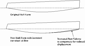
At this point in the design stage a modification of the hull took place which involved the beam to be used. It was decided to reduce the beam slightly without increasing the maximum draught or rocker of the hull. To increase the hull volume the curvature of the rocker at the bow was increased slightly to accommodate for the loss in displacement when the beam was reduced as shown in Figure 2.2. This modification succeeded in reducing the beam with only a slight increase of wetted surface area which seemed to be acceptable.
Figure 2.2, Modification of rocker curvature
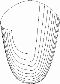
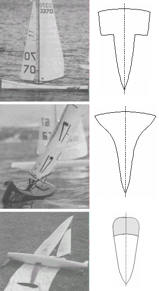
2.2.2 NOSE DIVING A large number of these slender model yachts have suffered from nose diving or pitching when running down wind. Due to this problem most of the models produced today adopt anti-pitching devices on the bows of the vessel, these range from chines, fins and excessive bow flare with high freeboard, some of which are shown in Figure 2.5. From the top down is a Chine bow section, Flare and high freeboard and finally a standard bow section with additional buoyancy added above bow, by using shaped foam. These appendages seem to help in some conditions but when the vessel pitches excessively these devices have failed to operate and the yachts have pitch poled stopping the yacht completely. This seems to occur due to the resistance of these appendages when they become submerged which cause the yacht to trip over its bow, which can result in structural damage if this occurs at high speeds. Obviously if the resistance in the bow could be reduced to a minimum the boat would not trip over the bow and pitch pole. This was experimented with in the test model by making the bow reasonably fine so that a wave piercing effect could be obtained as shown in Figure 2.3.
Figure 2.3, Wave piercing bow sections
This approach has been adopted in the past by full size catamaran designers who have reduced the number of appendages at the bow section to reduce the buoyancy and therefore the resistance when the bow begins to trim. The idea behind the concept is that when the vessel trims bow down she will correct the trim problem her self without the need for appendages, and also the speed of the vessel will not be reduced considerably, unlike in the model situations where the yachts have been caused to stop completely in the water. In the design of the test model it was decided to adopt this concept as it would be advantageous to examine the effect of this technique when applied to monohulls. The bow sections on the test model were reduced to allow a wave piercing effect and a freeboard of 0.125m was used at the bow so that the deck would not become submerged if the bow trimmed excessively.
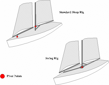
2.2.3 SAIL AND RIG CHOICE Another reason for the nose diving on the models can be seen when you examine the sail area being used on these slender yachts. The rule allows a maximum sail area of 0.516m², most model yacht sailors always use full area rigs in all conditions. This could account for the prolific accounts of nose diving with these vessels. It seems obvious that as the models become lighter and thinner they will not require the maximum sail area in all conditions to obtain the same speeds. To experiment with this idea the sail area on the test model was reduced to 0.484m². Another possible reason for the nose diving which is linked to the rig of the vessel is the type of rig which most of the models use. Most of the racing models use the Swing rig design which allows a more efficient sail set when the yacht is sailing at various angles to the wind as shown in Figure 2.4, since the slot between the two sails on the standard sloop rig varies as the sails are sheeted out. Since the Swing rig is more efficient it produces more lift and therefore a greater pitching moment when the vessel is travelling in most directions when compared to a standard sloop rig. Also the Swing rig requires the position of the centre of effort (CE) to be positioned further forwards as this type of rig requires a greater percentage lead. All rigs produce a down force and the further this is away from the centre of buoyancy the greater the moment it creates. This moment adds to the pitching moment, and therefore since the CE of the Swing rig is positioned further forwards, the net pitching moment is increased. Due to the high pitching moment that is generated by Swing rigs it was therefore decided to adopt a standard sloop rig which would hopefully reduce the pitching moment.
Figure 2.4, Sloop Rig & Swing Rig
2.2.4 KEEL AND RUDDER DESIGN The Keel and Rudder design were standard to model racing yachts with the length of the keel being kept at 0.457m, to account for the lack of stability provided by the hull. It should be noted that this keel length is not excessive in respect to models as keels up to 0.533m have been used by some vessels.
2.2.5 CONSTRUCTION The construction of the model yachts is also critical to their performance. Since the displacement is quite low when compared to standard wide beam models extra care has to be taken to achieve a high ballast ratio. A reasonable value for the ballast ratio is around 70% for racing yachts and it is very hard to increase this without reducing the strength of the hull, or by using expensive materials such as Carbon or Kevlar.
The hull was constructed using a method which is becoming quite popular and is known for producing light hulls without too much expense. The method consists of strip planking 1/32 Balsa planks over frames and only glueing them to each other and not the frames. The reason for this is that when all the planks have been assembled the planks are lifted from the frames and you are left with the correct hull shape weighing in at 0.11kg. Balsa and Ply bulkheads were then installed at areas around the mast step and the location of rigging connections. The hull was then skinned in a light layer of fibre glass cloth and epoxy resin, as the balsa although light is not very strong. The internal structures were then coated in epoxy to add some strength but mainly to water proof the hull. At some points along the hull in between bulkheads there was still some flex in the hull. To reduce this 0.05m wide Carbon Fibre tape was used to stiffen the hull and also keeps the weight to a minimum, this tape was also used around the hull under the mast to ensure no structural damage would occur. Balsa inwales and deck beams were then installed and the rudder shaft, keel box and frame work for taking all the mast a rigging loads was fitted. A ply deck was then fitted and sealed with epoxy resin. The internal structure is shown in Appendix 1.
It was decided to make the hull as waterproof as possible so the rudder shaft was taken through the hull and up through the deck. Radio equipment was installed in the standard watertight Pot in the deck and the winch was installed so that the drum was through the deck to make the sheeting system as simple as possible and also to reduce cost. The servo operating the rudder was fitted below deck and the push rods were replaced by the flexible Snake system which means the servo does not have to be aligned with the rudder and is also water tight. The keel and rudder were shaped by hand from balsa blocks and a ply spar was fitted in the keel to reduce bending. The rudder was given a single skin of glass fibre cloth in epoxy resin, while the keel was given four skins with the weave running down the keel and at 45º to reduce twisting. The keel is fitted to the hull in a keel box and is secured by means of brass bolt through the deck. Aluminium chain plates and mast step were then constructed and were attached to the hull after the hull had been sprayed. The mast is carbon fibre and weighs 0.22kg which helps to reduce the weight considerably. The booms were constructed from Balsa/Ply laminate and standard fittings were used for the vang and bottle screws. Rigging is multi-strand plastic coated stainless steel for the shrouds and jib stay, and 37kg Dacron cord was used for the back stay and the sheeting lines. Sails were constructed from a light transparent film which is reasonably easy to work and is a lot easier than using a woven cloth.
When the vessel was weighed the required amount of lead gave a ballast ratio of 66% which was acceptable. The cost of the model was not considerably high as some of the equipment was taken from other models, but an estimation of the cost of the materials with fittings required to construct the yacht would be around £150, the cost of the radio equipment can vary from £50 to £250 depending on the persons needs.
One of the major points that must be remembered is that this model is designed for sailing on fresh water and not the sea. The main reason for this is that the salt water can destroy the radio equipment, and you also have to be careful what materials you use for fittings, as salt water will corrode some model fittings. It is obvious that sailing on the sea with waves would have been more advantageous but this would have meant increased production time, as you have to ensure that the hull is absolutely water tight, and also there is the risk of increased all up weight which would effect performance, which may have resulted in the need for lighter construction materials like Carbon Fibre for the hull, which would have increased the cost considerably as Carbon Fibre is £28 per m².
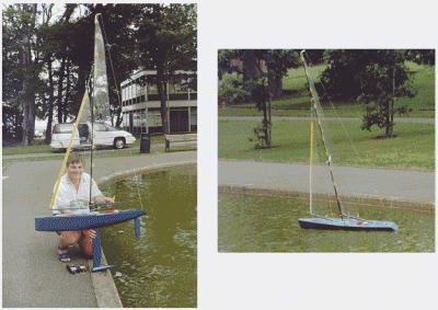
The test model is shown in Figure 2.6 sailing and with designer, this also gives an impression of the size of the model.
Figure 2.5, Anti-pitch devices
Figure 2.6, Test model (Dreams) and her designer
2.3 RESULTS FROM THE SAILING TRAILS The sailing trials with the model yacht provided some very interesting results. The performance of the vessel was impressive with very good speed in very light winds. The nose diving problem which was expected with this type of hull did not appear as much as had been expected. The yacht would start to trim bow down when it was overpowered in a gust but it would recover with little reduction in speed. When watching the model in an overpowered condition it was easy to see that a model with bow appendages could easily be stopped due to the resistance of the appendage as the speeds were quite high.
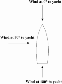
The vessel seemed more susceptible to bow down trim when sailing at angles of around 130º to the wind illustrated in Figure 2.7 but this is where you would expect large pitching moments to occur. The performance of the vessel when sailing directly down wind was good but was not as good as it was when sailing in other directions to the wind when compared to wider models of the same class. This could be put down to the planing effect which the wider vessels sometimes experience when running down wind, other reasons could be to do with appendage drag due to the long keel.
Figure 2.7, wind directions
The yacht showed a good pointing ability with very little leeway which could be attributed to the large rocker on the hull which will give good directional stability.
The reduced sail area did not seem to hamper the vessel at all and obviously helped in reducing the nose diving. One important point that did arise from the tests was that of loading from the low shroud base. The mast was found to be under very high compression loads as the metal pin holding the mast to the deck step was bent even in light wind conditions shown in Figure 2.8. No structural damage was found on the hull which is probably due to the frame inside the hull.
Figure 2.8, Mast pin damage
The heel angle of the vessel was found to be quite high if the large aspect ratio rig was carried in stronger wind conditions. The major point which should be remembered with this type of vessel seems to be that the larger rigs can not be carried for too long, once the wind speed starts to increase, as the large aspect ratio rigs have the centre of effort very high, and this coupled with a high wind speed creates a very high heeling moment causing the yacht to heel excessively. Therefore shorter rigs have to be used even though the wider vessels may be carrying their largest rigs, as their hulls provide additional stability and therefore righting moment. Obviously the area of the sails will also effect the heeling moment and since the sail area was not at its maximum this would have reduced the heel angle slightly. Another problem that did seem to occur in some conditions was that of loss of speed when coming out of a tack. No real reason has been found for this behaviour and the only way that it was found to compensate for this behaviour is to "crack" the sails to build up some momentum.
2.4 ANALYSIS OF TEST RESULTS When looking at the results from the sailing trials it does seem that the choice of rig is quite critical to these types of vessel if excessive heel angles are to be avoided. The nose diving problem seems to be not as bad as expected and it seems that using a wave piercing bow section does give better performance with respect to pitching. The reduced sail area also seems to help in the area of pitching and does not seem to adversely effect the speed of the vessel.
From the model test it is clear that the rig loading on one of these slender yachts is very high, and this will probably be one of the major design aspects which will have to be considered.
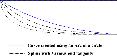
One possible reason for the improved performance over normal models could be down to the method used for producing the hull. The hull for the test model was designed on a computer hull form design package called HullCAD. This piece of software uses a B-Spline surface to model the hull form in an attempt to induce a good amount of fairness. Most models are designed and built by people who do not have the facilities to use these pieces of software and so other techniques must be used. Some of the model designers use arcs of circles to produce the rocker and hull sections where normally this is done using splines. This could be the reason for some of the pitching problems, as the hull forms that they are producing may have buoyancy distributions or centre of gravity positions which could be less desirable. If a large proportion of hull volume is found towards the centre of the yacht, and very little towards the ends, the hull form will provide very little resistance to trimming by either the bow or the stern. The position of the centre of gravity is related to the centre of buoyancy, if the centre of buoyancy is positioned well behind the location of the keel, the designer is going to find it very hard to position the lead bulb in a location either vertically below the centre of buoyancy, or slightly aft. This would result in the yacht exhibiting bow down trim when at rest and would exaggerate any pitching that occurred. Figure 2.9 shows that by using an arc to define the rocker or the waterline, will distribute the buoyancy away from the ends of the vessel. If now the same curve is produced with a Spline the designer is able to introduce more buoyancy towards the bow or stern of the vessel by adjusting the end tangents. The result of using a Spline is that the moment to cause trim can be adjusted by modifying the water-plane shape, and also the centre of buoyancy and centre of flotation can be controlled accurately. One factor that could uphold this reasoning is that one design of model production racing yacht called Paradox designed by Graham Banttock, has been very successful, and this vessel is designed using computer software.
Figure 2.9, Control available when using splines
|

