|
Vulcan
Cockpit Instruments |
|
DOWNLOAD ADVICE
This page is graphics intensive and will take a long time to download
fully. Please be patient. |
Use the mouse to discover what the
controls inside the Vulcan were used for. If the pointer turns to a finger left
click to discover more!

Main flight deck

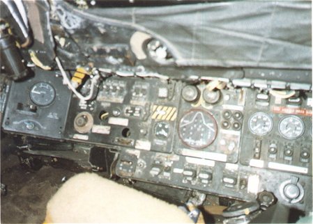
Controls to the left of the Captain
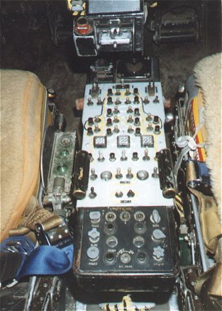
Centre Console
Controls to the right of the Co-Pilot
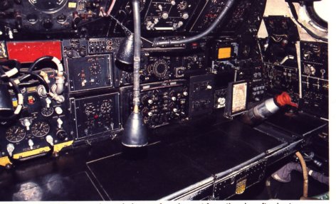
Rear Crew Compartment

Throttles
These were used to control the amount of thrust delivered by each of the
four Olympus engines.
Power Supply Indicator
Used by the rear-facing crew to
check the status of the power supply to the navigational & bombing computer.
Track
Control Unit
The track control unit for the
military flight system (mfs).
AEO
Navigation Window
A small window used for
navigational purposes. A similar window is located on the opposite side of the
aircraft, where the Nav Radar operator would be seated.
Altimeter
The instrument which indicated how high from
the
ground the aircraft was flying.
Power
Supply Panel
The main aircraft power supply
panel . 200v 400hz AC is the main source of electrical power in the Vulcan Mk2.
The normal power source would be from the four jet-engine driven alternators,
any one of which was capable of providing enough electricity to power all the
aircraft systems. A ground power source could be used before the engines
were started. While in the air, an Airborne Auxiliary Power Plant (AAPP) or Ram
Air Turbine (RAT) could also be used. A combination of electromagnetic
"dolls eye" indicators, warning lights and dials help to maintain a
constant supply of power to the systems. Remember, the Vulcan is an all-electric
aircraft. If all the power was to fail the fate of the aircraft was sealed.
TACAN
Indicator
The TACAN (Tac(tical) a(ir)
n(avigation) system is
an electronic ultrahigh-frequency navigation device for aircraft
which gives a continuous indication of bearing and distance from a transmitting
station. This is used to aid navigation.
Joystick
The level used by the Captain or Co-Pilot to manoeuvre
the aircraft. The large "chinaman's hat" is the trim control used to
make small adjustments to the trim of the aircraft to help it fly straight. The
small button on the right of the joystick was the intercom switch which allowed
the pilot or co-pilot to talk to other crew members.
The yellow and black switch would be used to disconnect the "artificial
feel" systems.
Panel
Dimmer Switches
Used to control the intensity of
the lighting on the chartboard lights.
Peddle Adjuster
This knob could be used to adjust the distance
the peddles
were from the seats.
Thus allowing pilots of different sizes to fly the Vulcan more easily.
Airspeed Indicator
This instrument would give information to the
crew about how fast the Vulcan was travelling.
Accelerometer
A device which measures the speed
of acceleration
(or deceleration) of the aircraft.
Fuel System Control Panel
The Vulcan could carry a lot of
fuel. The distribution of this fuel had to be carefully monitored by the crew to
ensure that the aircraft's centre of gravity did not move, and cause handling
problems.
Compass
Isolation Switches
Used to isolate the navigational
compass.
Grab Handle
The centre console was only
extended when both Captain and co-pilot had been strapped in. Although the Vulcan
is a large aircraft, the room given to the crew is small. It would be impossible
for the pilots to gain access to the cockpit if the centre console was always
extended.
Bomb Bay Fuel Tanks Control Panel
On long sorties the Vulcan could
use a fuel tank housed in the bomb bay. This panel would be used to direct the
fuel from the bomb bay fuel tank either directly to the engines, or to one of
the other fuel tanks housed within the wings.
Rudder Peddle
These are controlled by the
pilot's feet
to alter the heading of the aircraft.
Lamp
Used by the Nav-Plotter or Nav-Radar
to
illuminate instruments, maps or charts.
Tanks Full Indication (in flight refuelling)
Tells the crew how much fuel they
have in the fuel tanks.
Tank Pressure Indicators
Indicates the pressure in the fuel
tanks. This is useful when the distribution of fuel around the aircrafts tanks
has to be altered in order to shift the centre of gravity.
Control Surface Indicator
As the Vulcan is an all-electric
aircraft (there is no physical linkage between the cockpit joysticks and the
rudder or elevons) this instrument shows the crew the position of the control
surfaces whilst in flight.
Mach Meter
Used to indicate the Mach velocity
of the aircraft.
Mach 1 equates to the speed of sound.
Beam Compass
Used to aid navigation.
Engine RPM Indicators
These indicate the revolutions per
minute of all 4 Olympus engines.
If the RPM gets too high damage of the engine could result.
Rate of Climb Indicator
An instrument which would display
the
rate of climb (or decent) of the aircraft.
Oil Pressure Gauge
Use to display the oil pressure.
Low oil pressure could mean a loss of oil, which in turn, could lead to engine
seizure.
Engine Temperature Indicators
Instruments used to give the crew
an indication of the temperature of each jet engine.
MFS Selector Unit
The military flight system (mfs)
can be thought of as a early relative to the integrated computer monitor
cockpits of modern airliners. One instrument displayed aircraft attitude (slightly
miffed, or fairly relaxed!!) with the other displayed directional
information and steering demands.
Altitude & Auto Land Phase
Indicator
The Vulcan was the first four
jet-engined aircraft to be fitted with an automatic landing system. This
instrument would give feedback to the crew as to the height of the aircraft, and
whether the auto landing mechanism was activated.
Flight Refuelling Pressure Gauge
This tells the crew the pressure
of the fuel in the tanks during in-flight refuelling. If the pressure of the fuel
being pumped from the "feeder" aircraft became too high the fuels
tanks could have ruptured.
Captain's Seat
The seat to the left of the cockpit was where
the Captain would sit during sorties.
Co-Pilots Seat
The seat to the right of the cockpit was where
the Co-pilot would sit during the flight.
Airspeed Indicator
Used to inform the Captain or
co-pilot the present air speed of the Vulcan.
Artificial
Horizon (Standby)
Used if the cockpit was completely
blacked out (likely if a nuclear flash was expected), the artificial horizon
would allow the crew to determine the pitch and yaw of the aircraft without
having to take a visual reference from the ground or sky.
Bomb Bay Tanks System Control
Panel
A bank of switches used to control
the movement of fuel from the auxiliary bomb bay fuel tanks to the main fuel
tanks.
Nitrogen Purge (in flight refuelling)
Activating this control forces any
fuel left in the refuelling probe into No 2 tank. Nitrogen is used, as it is
non-explosive.
Dimmer Switches For Probe
Illumination Lamps
The refuelling probe has two
lights for illumination positioned in the nose of the aircraft. To prevent glare
during air-to-air refuelling the dimmer switch could be activated. Similar to domestic dimmer switches.
Intercom Control Unit
Used to adjust communications with
the
crew members or ground crew.
Autopilot
Control Panel
Used to control whether the
auto-pilot was controlling the flight of the Vulcan. The auto-pilot was a
valuable instrument during long flights.
Engine Start Switches
As the name suggests these
controls allow the Captain to start the Olympus engines once the pre-flight
checks have been completed.
Navigational Control Unit
Part of the complex equipment
carried by the Vulcan to ensure positioning of the aircraft could be
established. Especially useful when travelling over tundra, such as that
expected when flying towards the heart of the Soviet Union.
Brake Chute Control
This switch controlled the
deployment of the brake parachute.
First position activates the braking chute.
Second position releases it.
The braking chute must always be jettisoned before the Vulcan comes to a halt.
Director Horizon
The director horizon unit computes
the necessary roll and pitch attitudes needed to intercept and maintain
headings, courses, attitudes, and altitudes. These computations are then
displayed through the flight director horizon as steering commands, greatly
simplifying instrument flight.
ADF Bearing Compass
The automatic direction finding
bearing compass used radio signals to "home" in on friendly airfields.
Useful in poor weather conditions.
Ejection Handle
Should the Vulcan develop a serious fault the
Captain and Co-pilot could both eject safely. Unfortunately, the other crew
members were no so lucky, and had to try and open the entrance hatch to escape.
Auto-Pilot Control Panel
The Vulcan was designed for long
range missions, during much of this time the aircraft used its autopilot to head
towards its destination, thus giving the Captain and other crew members valuable
time to concentrate on other tasks.
Engine Anti-Icing Control
These control govern how much
engine exhaust is circulated around the leading edge of the wings to prevent ice
from forming at high altitudes.
Nav Heading Unit (HRS)
The Heading Reference System was
used to ascertain the direction in which the Vulcan was currently travelling.
Indicator Control Unit
Sorry, I can't tell you much more
about this device I'm afraid.
Tanks Full Indicator
An instrument which indicates when
the Vulcan's fuel tanks were full. Used during in-flight refuelling.
HRU Power Failure Indicator
The Heading Reference Unit (HRU)
is a self-contained strapdown inertial navigation system. If power was to fail
on this device the Vulcan could, if the crew were not aware of the failure,
become lost. If power was interrupted to the HRU this would be indicated on this
instrument.
Tail Warning Radar Control Unit
The orange rectangle was used to
show the presence of enemy missiles or aircraft approaching the Vulcan from the
aft. Depending on the frequency used by the incoming missile or aircraft, a
number of countermeasures, selected by other control boxes in front of the AEO,
could be selected to act as counter-measures to the threat.
GPI Mk VI
The Ground Position Indicator
allowed the crew of the Vulcan to gain accurate knowledge of where the
ground was in position to the aircraft. This was especially useful when flying
low-level sorties.
Landing Light Switches
Use to activate the landing lights
which are located in the wings of the aircraft. The switches have three
positions, one for landing, one for taxying (lights extend further from the
wings,) and one for fully retracted (lights off).
Knee Pad Lamp
The Captain and co-pilot would
often carry maps in the pockets of their flight suits. When seated they were
able to use this light to read the map without having to remove it from their
uniform.
Periscope
Used by the AEO to view the
underside of the aircraft to ensure any missile being carried had detached
safely
from the Vulcan. Also used to view behind the aircraft for a visual check of the
airspace.
Abandon Aircraft Illuminated
Sign
This was one sign the AEO, Nav
Plotter and Nav Radar did not want to see illuminated. If the aircraft had to be
abandoned the Captain or co-pilot could use this to advise the rear crew to
quickly escape via the entrance hatch. Remember, only the Captain and co-pilot
had ejection seats.
Unknown Instrument
Despite extensive research I have,
so far, been unable to find out what this does. If you know, please inform me.
Thanks!
Back to previous page
|