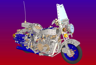
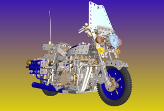
Kawasaki 1000 P "ChiPs" motorcycle
By Anthony and Christopher Els
Drawn in Pro Desktop by Anthony Els
 |
 |

By Anthony and Christopher Els
Drawn in Pro Desktop by Anthony Els
|
|
The model is both a nostalgic reconstruction as well as a complex exercise in CAD. Many years ago, my brother Christopher and I spent hours glued to the TV watching California Highway Patrol (CHiPs) episodes. In 1982 I received a plastic 1000cc Kawasaki CHiPs motorcycle model kit produced by Revell, which was quickly glued together willy-nilly. It eventually was stood on, becoming distorted and mangled (as many kids toys eventually become). In about 1987 (and after accumulating quite a bit of Meccano), my brother and I decided to build a Meccano version, based on the remaining mangled parts of the plastic kit (Of which I still have the remains today!) At that stage, some Meccano components in the engine were held together literally by string due to lack of parts/technique! It did however receive favorable comments when we presented it at the first Meccano club meeting we attended at the Johannesburg Meccano hobbyists in Johannesburg.
Since then, the model underwent a rebuild in 1994 for the Rand Easter show. Then, in early 2000, I started experimenting with drawing parts using a package called Pro Desktop. I did'nt have far to look for a subject! Amongst the first parts drawn were those on the motorcycle and it wasn't long before I had made some headway with the front suspension. The project was then shelved due to other distractions, although I knew I would eventually get around to drawing it completely. By 2002 I had completed various Meccano CAD projects, but the motorcycle always remained incomplete. Until now.
The TV series made the Kawasaki police bike famous around the world. An unintentional marketing stunt par excellance. The model represents a much sought-after 1981 version. The police motorcycles differed from civilian ones by the presence of the obvious rear mounted radio, the lights, siren, colour, etc. Unseen modifications relate to engine modifications: from larger ports and pistons to polished intakes (some say they were opened up to 1200cc, but this is more likely urban legend). At the time they were really performance pocket-rockets. Many of these cycles are still in use to day and are highly prized collectibles. There are still various clubs who dress up as cops and go riding around the countryside. (No, at this point you can't start singing YMCA....)
An MO Mk II (or III) powers the rear wheel via chain. All-round suspension, complete with functional front and rear disk brakes add a degree of realism, but are more of a token effort than of any real stopping power. The flat windshield is different to the more familiar molded/windswept ones found on later police cycles. Triangular clear plates would have come in useful here! I have added some of the newer French parts and a few narrow fishplates from Exacto for improved detailing. Another feature is the multiple component construction.
You might argue that lots of the model features compromise on the "real thing". For example, the chassis is marginally higher than it needs to be, due to the chassis strip construction. The angle of tilt of the engine is slightly too large and brake calipers are not floating, like on the real thing, etc.. What you must remember is that the model was built when we were only 12 and 14 years of age, when a true sense of scale and engineering principles still required some refinement! If I were building it from scratch today, many things would be done differently. That is not to say that its a bad model! There is still large scope for experimentation and improvement by modelers:
The original model had a (somewhat fiddly) 2 speed gearbox, actuated by a gear lever in appropriate position (not present in this model plan). The hand accelerator was attached to a potentiometer, which allowed the motor to rev as the grip was rotated. At the same time via cable, the rev counter (a piece of wire trapped behind the head of a screw) would also climb the revs proportionally. Also fiddly, and not included in the imodel plan. I suppose if you were really dedicated, it might be possible to build the entire frame from formed 4mm wire, which would be far more proportional since parts would sit INSIDE the frame rather than on top and below. (I might do a CAD version of this). It is also possible to outfit the model with the appropriate sound effects from one of the IR kits remote control. Failing that, a recording of the real thing might do nicely. I will present a compact DIY circuit for 30 second solid-state sound recording and playback in a future article. Suitable LEDs can be attached inside the modern plastic parts to act as the main lights of the cycle. Batteries can be housed inside the saddle bags and radio. For exhibition purposes, a base was originally constructed to allow both wheels to rotate.
Details such as siren (attached to the front bumper bar, right hand side) and stand (either pull-back or tilt), spark plugs wiring, lighting, motor control, etc. are left up to the imagination of the builder. As mentioned previously, one of the sound effects tabs from the French IR kit can possibly be used for the public to press at exhibitions.
The list of improvements could go on and on!
The main challenge of drawing the model was not drawing the curved strips, but surprisingly getting them in the correct relative positions. In the realest sense of the word, the model was "rebuilt" in CAD from photos, using parametric modeling constraints and interactive components to ensure everything fits correctly and the frame bends variably if required. For instance, the width of the chassis depended on the width of the engine, which depended on the angle of the front spar of the motorcycle. Instead of pulling out a calculator and working out all the geometry, it is much easier to create the engine and the frame separately, then deform the frame to match interactively. Granted, the curved strips are one-offs and not modified flat strips, but who cares, the extra work of drawing them is worth it, and the one offs are filed for future use (much like my permanent collection of warped strips which sit in a separate box). Re this: Consider for example the warped 3.5" strip on the petrol tank!
Presentation is a mix of exploded drawings, assembley sequences, numbered parts and multiple views of fully assembled modules. I did not stick to one particular style of presentation, since it would have made things exponentially complex.
Pro Desktop parts (some 450 now) are still not posted on-line. Coming soon.
I tried extremely hard to avoid what South Africans are fond of calling "jippos", "maak-n-plans" or just plain shortcuts. All of the parts used in the model are standard in size and the model can really be constructed as shown.
No real warnings are given as to holes that must be left open during construction. Exact attention must be paid to each stage to avoid frustration and undoing of bolts to get things to fit.
Many of the collars in the model can be substituted using plastic spacers.
This next statement sounds so obvious, but there are important implications for saying it: the correct spacing between the two halves of the frame is decided by the following points only: The 1" double angle brackets at the rear, the rear wheel screwed rod (81), the carburetor, the front steering column and the front engine mounting points. All the others points must follow on from these.
You will no doubt complain about the way that the frame is constructed! It is unfortunate in that it lacks rigidity and relies on everything being tight. When constructing, try to keep the upper 3.5" strips parallel with the bottom 2" strips. Hand tighten all points on the frame. Once all the various modules are fitted, adjust and tighten well. It will take some time to get this part right!
Note the system used for the front suspension to hold it together: a 1mm wire is bent over at its end to form a small ball. The free end of the wire is passed through the bottom of each suspension damper, down the centre of the keyway rod. The small ball of wire is trapped against a shoulder bolt screwed into the damper. The free end of the wire is then attached to a screw on a collar on the steering column.
Disc brake performance may be significantly improved by using a screw-actuated type of some kind. Note that the front left disk free-wheels. You can either glue or solder the disk to the front wheel. If a larger disk (or gear blank) is used which is more to scale, then two of the radial holes can be used to bolt the disk to the front wheel, with larger clearance for the pads.
Note that plastic rods have been used in certain parts of the model to represent "bumper bars". These can be gently heated and bent into shape. Alternatively, use large (4mm) chromed coat hanger wire. The joins between bumper bar T-junctions are non-existant at present, but the builder is left up to his/her preference to do something about it!
The exhaust currently uses a plastic plate that is heated and rolled into shape. Alternatively, you may consider a pair of rolled up plastic "wings" from the Crazy inventors bat set for the two exhausts.
PREVIOUS | NEXT
INTRODUCTION
CONSTRUCTION:
To download the file(s) you want, either follow the appropriate link(s) below or right click on the link and select "Save target as ..." to save each file to your local drive.
HTML files (chiphtml.zip, 18K)
Download all the "illustrations" ZIP files and the "HTML" ZIP file to a new directory on your local drive. Use your favourite "unzip" program to extract all of the files, then open the file "index.html" in your browser to view these web pages offline. These download pages have been set to black text on a white background to make printing them easier.
These instructions and the accompanying pictures are copyright material, and all rights are reserved. They are made freely available to Meccano modellers on condition that they are not copied and distributed in any form for sale, whether or not the sale is for profit or merely 'at cost'. Nor may they be distributed in incomplete form. Printed copies may however be made freely for personal use.
![]() ©
Anthony Els January 2003, meccano22@hotmail.com
©
Anthony Els January 2003, meccano22@hotmail.com
"The Meccano Model Library" is owned and run by Chris Bourne, cfpb@lineone.net
Website designed and maintained by Donna Smillie, dms@zetnet.co.uk
http://www.users.zetnet.co.uk/dms/meccano/chipsbike/index.html