The Gearbox
Designed and described by Paul Dale
Photographs by Brad Johnson
DESCRIPTION

Designed and described by Paul Dale
Photographs by Brad Johnson
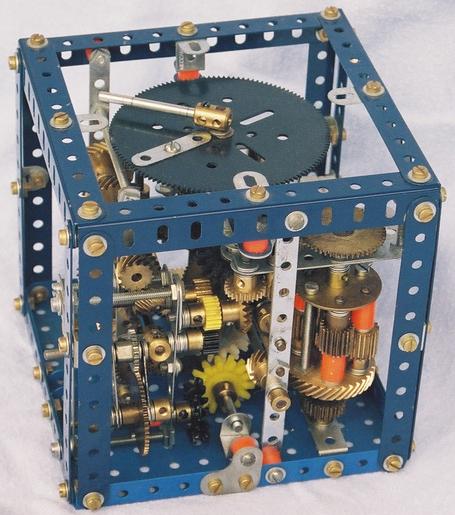
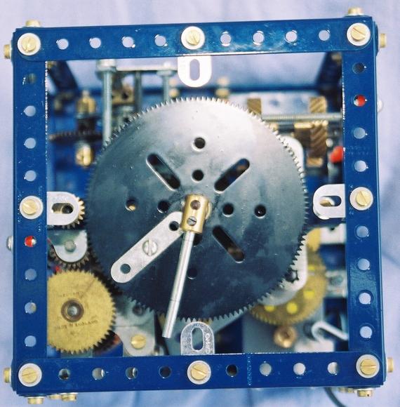
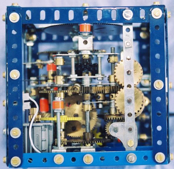
The gearbox is a fun model that might better be described as a box of gears arranged in a fairly convoluted manner. When set in motion it induces an almost hypnotic effect on observers. It began life as an attempt to see how many gears could be interestingly crammed into a small space. The top of the box is deliberately designed to resemble a clock face. The hands travel in approximately the correct ratio, however they move erratically. The minute hand jumps forward about a third of a revolution before pausing briefly and repeating. The hour hand progresses forward but it does so by oscillating energetically back and forth.
When on display I include a card with some quick questions for the visitors:
This model was definitely not designed. More accurately, it evolved and grew into its current form. Often when a new section was added in, several older modules required some reworking to avoid collisions and the regular too fine tolerances needed adjustment. The only real planning was a quixotic determination to stay close to the correct ratio between the hour and minutes hands.
(select image to view PostScript file)
The gearbox consists of a 5 1/2" cube constructed from 5 1/2" strips and angle girders and a pair of base plates. The box contains a total of fifty six gears of varying kinds and sizes and it weights a lot more than most people expect. The gears are supported by a myriad of small brackets, long bolts and narrow strips arranged, by necessity, in an ad-hoc manner. The actual gear chain is illustrated above albeit laid out flat rather than twisting through space.
Everything bar the tip of one short axle, is contained wholly within the cube for transport, however the minute hand dwell mechanism does extend beyond the confines of the box during operation.
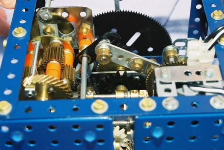
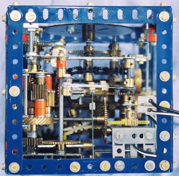
The erratic motion of the hour hand is produced by the differential. The main drive enters this via the lower half shaft and exits through the upper. The drive then goes through a number of gears until finally the 133 tooth gear with the hour indicator is powered. In the above figures the dwell production linkage is illustrated. The dwell is induced by gearing the cage of the differential to a crank which is driven by a small eccentric. This causes the cage to rock back and forth and thus to impart the oscillating motion to the hour hand.
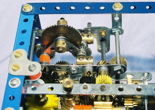
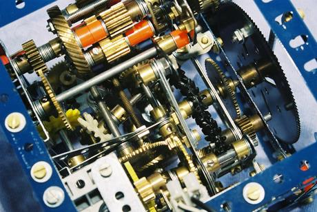
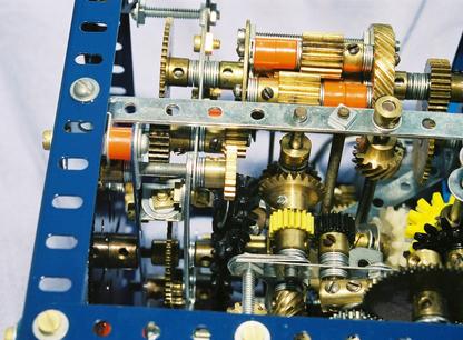
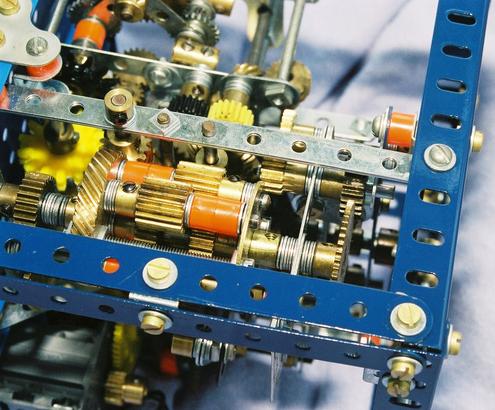
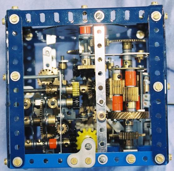
The minute hand gains its irregular motion from the mechanism illustrated above. This neat mechanism produces a positive drive to the lower output shaft that pauses for a about a third of the rotation of the upper input shaft and which then rotates rapidly to catch up to the input. If the custom short couplings aren't available, use normal ones and substitute the pair of input axles with short threaded pins. From the output shaft, the gear train continues through six variously coloured multi-purpose gears to the top of the model and the minute hand. In the background of left side view below and in the latter two figures above the multitude of meshing possibilities available with these gears is demonstrated.
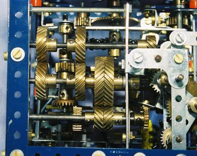
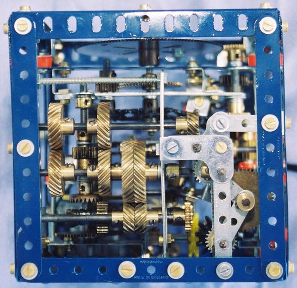
The drive from the motor to the rest of the gearbox begins using a number of gears and pinions to reduce the speed to something manageable is visible in the rear view below. There is also a take off for the eccentric that drives the differential cage. Subsequently, this drive passes through the left and right handed helical pairs see above before splitting into the hour and minute drives as seen in the centre of the front view seen below.
There are only two unnecessary gears in the box. Specifically, two of the pinions in the differential are redundant. Despite first appearances, all the helical gears are essential to the unit's correct operation. Examination of figures these gears in various views reveals that the upper and lower shafts supporting these gears are not constrained by collars or bosses. These pairs of helical gears are arranged as chevron gears which are self cantering and counteract any lateral motion!
These instructions and the accompanying pictures are copyright material, and all rights are reserved. They are made freely available to Meccano modellers on condition that they are not copied and distributed in any form for sale, whether or not the sale is for profit or merely 'at cost'. Nor may they be distributed in incomplete form. Printed copies may however be made freely for personal use.
![]() © 2004, Paul Dale (pauli@moreton.com.au)
© 2004, Paul Dale (pauli@moreton.com.au)
"The Meccano Model Library" website is owned and run by Chris Bourne (cfpb@lineone.net)
Website designed and maintained by Donna Smillie (dms@zetnet.co.uk)
http://www.users.zetnet.co.uk/dms/meccano/dale/gearbox/index.html