NUTTY and his PACHYDERM
by Arup Dasgupta


by Arup Dasgupta
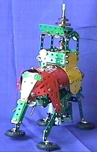
This is a fun model based on the walking mechanism from the French set 9550 Mammoth. It uses parts from the Red and Green era (and a bit of yellow for the 'gold' decoration). I have used a non-Meccano motor to drive it but a modern French Meccano motor can replace this if required.
Start the construction with the motor as shown in figure 1. Extend towards the tail with two 1x3x1 double angle brackets (DAB) as shown in figure 2. Fix a 1x5x1 DAB and trunnion as shown to the free lugs of the 1x3x1 DABs. The lugs of the 1x5x1 DAB will provide the pivots for the rear legs and the trunnion will provide the pivot for the tail assembly. The motor shaft carries a 15T pinion. A 3-hole angle girder is fixed to the 'front' end of the motor bracket.
 Figure 1 |  Figure 2 |
Attach two 3-hole angle girders to the angle girder attached to the motor as shown in figure 3. Fix two flat trunnions and a 1x3x1 DAB between the two flat trunnions. Two corner gussets and a 1x3x1 DAB complete the front of the chassis.
 Figure 3 |  Figure 4 |
A 3-inch axle journalled in the middle holes of the two flat trunnions carries a 50T contrate, which meshes with the 15T pinion on the motor shaft. A worm is mounted on the axle, which meshes with a 57T gear wheel on a 2.5" axle rod journalled in the longer arms of the corner gusset. See figure 5.
 Figure 5 |  Figure 6 |
Figure 6 shows the 1.5" pulleys mounted on the drive shaft spaced from the chassis by 2 or 3 washers. A long bolt no. 111 is fixed to each pulley such that they are in opposite positions. The forelegs and the links to the rear legs use the long bolts as pivots.
 Figure 7 | |
 Figure 8: Head outer view |  Figure 9: Head inner view |
The forehead consists of two 3x5 hole triangular flexible plates back to back. The trunk consists of three 5-hole strips attached to two double brackets. Two 3x5 hole triangular flexible plates (A) are fixed to the sides of the trunk. These will form the sides of the head of the elephant. The tusks are long threaded pins (115a) bolted to angle brackets. The desired angle of the tusks is obtained by fixing the angle bracket to a second angle bracket as shown in figure 7. A 5-hole strip (B) is curved and attached to the forehead by a single bolt (C) as shown in figure 8. The two 3x5 hole triangular flexible plates (A) and two 5x3 flexible plates (D) are bolted to the extremities of the 5-hole curved strip as shown in figure 9. Each 3x5 flexible plate is bent inward such that its inner corner can be bolted to the centre hole of the other 3x5 flexible plate.
The outer holes are made to coincide and will be attached by a bolt to the main body later while attaching the mahout.
 Figure 10 |
The front support is made up of two flat trunnions bolted nose to head. A 1x3x1 DAB is attached to the lower end of the support. The upper end carries a 1x7x1 DAB. The rear support consists of a trunnion and a flat trunnion and a 5-hole strip sandwiched between them. The trunnion and flat trunnion are nose to nose. The upper end of the flat trunnion carries a 1x7x1 DAB. Two 11-hole strips (E) form the sides and anchor the flexible plates forming the body of the elephant.
 Figure 11: Inner view of the body laid out flat. |
The body consists of two 11x5 hole flexible plates (one red and one yellow), two 5x7 hole triangular flexible plates (TFP) for the rump and two 4x7 hole TFPs for the cheeks arranged as shown in figure 11. The strips (E) and the flexible plates (D) forming the top of the head are also shown in figure 11 to illustrate the attach points (F) for the supports and the head to the main body. A formed slotted strip completes the rump. Bend the 5x7 TFPs towards the formed slotted strip such that the holes (G) align with the slot on the formed slotted strip. Fix with a bolt. Figure 12 shows the constructed views. The ears are 3x7 TFPs attached to the cheeks as shown. Two yellow semi-circular plates form the fringes of the 'golden' decorative sheet on which the howdah is fixed.
 Figure 12a: The body attached to the supports. |  Figure 12b: The front view with the ears. |  Figure 12c: The rump. |
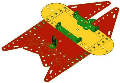 Figure 13: Body outer view, showing position of mahout and howdah. |
The maharaja and his howdah have to be built together. Figure 13 shows the position of the howdah and the mahout on the outer side of the body. The 1x2 angle bracket forms the body of the mahout and the two 1x5x1 DABs that form the base of the howdah.
The bolt that holds the rear DAB also holds the formed slotted strip and a 2x2 corner bracket, which represents the maharaja's folded legs as he sits cross-legged on the howdah. The back of the howdah is formed by two 1x5x1 DABs. Figures 14a through 14e show the construction of the maharaja. Two rod and strip connectors are bolted to a coupling with a 28.5mm bolt. The coupling is attached by a bolt to the back of the howdah spaced by two washers and a fishplate. The arms are fork pieces (not shown).
A 1-inch triangular plate is bolted to the front of the coupling. The bolt is spaced using shiny washers that act as the maharaja's jewel. The head consists of a half-inch pulley with boss and a collar bolted to the fishplate using a 19mm bolt. The turban is a pinion (part no. 25) fixed in the boss of the half-inch pulley using a 19mm bolt spaced with washers.
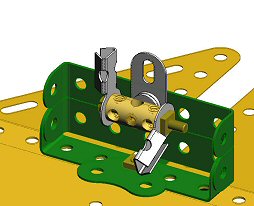 Figure 14a | 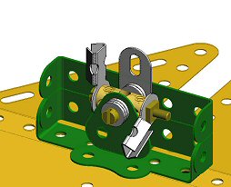 Figure 14b | 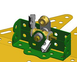 Figure 14c |
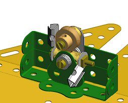 Figure 14d | 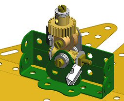 Figure 14e | 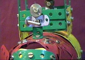 Figure 14f |
| Figure 14: The maharaja's (a) hands, (b) body, (c) neck, (d) head and (e) turban. (f) The mahout. | ||
A 3-hole strip attached to the 2x1 angle bracket forms the body of the mahout. The head is a half-inch boss-less pulley fixed to the top end of the 3-hole strip and the arms are obtuse angle brackets fixed to the middle hole. The elephant prod is a 28.5mm bolt attached to one of the obtuse angle brackets.
 |  |
| Figure 15: The howdah. | |
The front of the howdah also consists of two 1x5x1 DABs. Four 5-hole strips form the pillars. The sides are 3x5 hole flexible plates fixed so as to cover the gap between the platform and the curved back. A 5x5 hole flat plate forms the top and is attached to the pillars with 1x5x1 DABs. 5-hole stepped curved strips form the top decoration on three sides. The front is open with a 5-hole flat girder fixed to obtuse angle brackets to provide a sunshade. A bush wheel is mounted on the flat plate. A 2-inch rod fixed in the hub of the bush wheel carries a half-inch, a one-inch and a 1.5-inch pulley to represent the curved top of the howdah. The top of the rod carries a right angle rod and strip connector as a pennant.
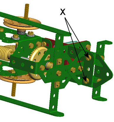 Figure 16: Rear attachment. |
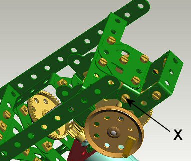 Figure 17: Canted front bracket. |
The body frame is attached to the chassis by four nuts and bolts (X) as shown in figure 16. The front support has to be canted back slightly as the 1x3x1 DAB will not sit square on the corner gussets. See figure 17. The 11-hole strips holding the body will thus be slightly tilted forward.
Figure 18 shows the legs and the walking mechanism adapted from the French Mammoth model. The forelegs of the elephant are made up of two 7-hole strips overlapped 6 holes. A 1x2 hole angle bracket forms the foot and it is braced with a 5-hole strip. The footpad is a 1" pulley with boss fitted with a suitable tyre and fixed to the angle bracket with a half-inch bolt. A 9-hole strip joins the front and rear legs. Two stepped curved strips overlapped all but one hole are fixed between the foreleg and the 9-hole linking strip. The upper hole of the foreleg and the end of the 9-hole linking strip are pivoted on the long threaded bolt on the 1.5 inch pulley. A collar and a washer are mounted on the bolt as spacers. Locknuts at the end of the bolt retain the legs and the linking strip. The rear leg is a 9-hole strip pivoted on its fourth hole from the top on the lug of the rear DAB using a screw with locknuts. The rear footpad is a 1-inch pulley mounted on a 1x1 angle bracket that is pivoted on the lowest hole of the rear leg using a screw with locknuts.
The tail is a 4-hole strip attached to a double bent strip with an obtuse angle bracket. The double bent strip is fixed to a 7-hole strip. The tail is pivoted on the rear trunnion with a 1x2 hole angle bracket. As the legs move the rear legs hit the 7-hole strip making the tail sway from side to side.
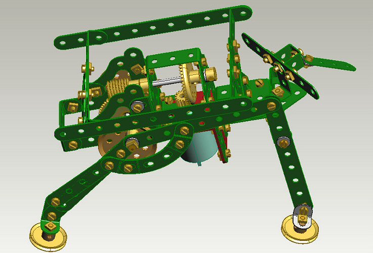 Figure 18: The walking mechanism and the tail. |
| Part | Qty | Part | Qty | Part | Qty | Part | Qty | Part | Qty | Part | Qty | Part | Qty |
|---|---|---|---|---|---|---|---|---|---|---|---|---|---|
| 2 | 2 | 12 | 6 | 24 | 1 | 45 | 1 | 77 | 1 | 126 | 2 | 214 | 2 |
| 2a | 4 | 12b | 2 | 26c | 1 | 48 | 5 | 90a | 7 | 126a | 5 | 215 | 1 |
| 3 | 5 | 12c | 5 | 25 | 1 | 48a | 9 | 103f | 1 | 133a | 1 | 221 | 4 |
| 5 | 13 | 16a | 2 | 27a | 1 | 48b | 2 | 108 | 2 | 142c | 4 | 224 | 2 |
| 6 | 1 | 16b | 1 | 28 | 1 | 59 | 4 | 111 | 3 | 188 | 4 | 225 | 2 |
| 6a | 1 | 21 | 3 | 32 | 1 | 63 | 1 | 111a | 7 | 192 | 2 | 226 | 2 |
| 9f | 3 | 22 | 5 | 37a | * | 65 | 2 | 111d | 2 | 212 | 2 | ||
| 10 | 1 | 23a | 1 | 37b | * | 72 | 1 | 115a | 2 | 212a | 1 | ||
| 11 | 2 | 23b | 1 | 38 | * | *37a and b and 38 as required. Rest, E&OE. | |||||||
In the end, let me thank Rob for the inspiration, Lynn for the scans of the model plans and advice on the working of the original. Anthony has to be thanked for the Meccano parts in 'ProDESKTOP' and also advice from time to time on the intricacies of the software. Thanks to all Spanners for encouraging me to write it up. There you are!
There isn't any. Please copy it, improve the model, and print it in your newsletter. I will be grateful if improvements are conveyed to me. And I will be in raptures if I get a copy of the newsletter which features the model. For those of you who are using ProDESKTOP I can send the des files so you can manipulate the model to get better views of the construction and the mechanisms.
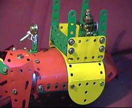
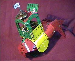
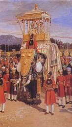
I am yet to learn how to bend plates and strips using 'ProDESKTOP' so I have used photographs of the actual model in such cases. The photos are taken from a video camera hence resolution is low but by using close-ups I have overcome this problem. Finally, another view of the model and a painting of the real thing for comparison.
 |  |
![]() © 2004, Arup Dasgupta (arupdg at sify.com)
© 2004, Arup Dasgupta (arupdg at sify.com)
"The Meccano Model Library" is owned and run by Chris Bourne (cfpb@lineone.net)
Website designed and maintained by Donna Smillie (dms@zetnet.co.uk)
http://www.users.zetnet.co.uk/dms/meccano/nutty/index.html