The BT Tower, London
by Nigel Pope

by Nigel Pope
The 1960s brought with them some radical architecture, both good and bad. The BT Tower was opened in 1965 by the Prime Minister, Harold Wilson, and was then the tallest building in London. It still dominates the Central London skyline, loved by some and loathed by others. I like its unusual looks and I think the architects did a really good job with what is, after all, a purely functional building.
The real tower was designed by G.R.Yeats and is 620ft (189m) to the aerial tip. The lower part of the Tower houses transmitting apparatus and the aerial galleries are above. At the top, is the Tower Suite with its rotating restaurant.
The restaurant used to be open to the public, but someone planted a bomb there in 1971 and so now the Tower is closed to the public for security reasons. The restaurant is still there and it still rotates, it is now used for BT corporate events and for charity phone ins. The view of London from the top is fantastic.
My model of the Tower is made almost entirely from scrap parts which came out of my Meccano junk box. These have been stripped and re-sprayed in blue and yellow (plus a few white parts). Of course, you can use new parts for your model, but I quite like renovating old parts and it is a lot cheaper. I did use modern French hex bolts. I think these are vastly superior to the old cheese head slotted screws.
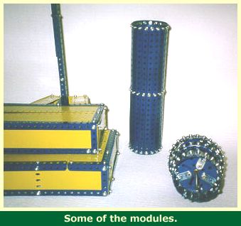
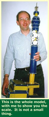
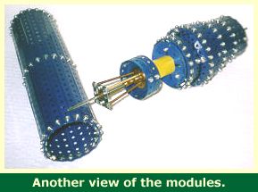
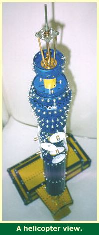
The model is made from modules which are made separately and then bolted together. The top part of the tower lifts off for easier storage and transport. I will describe the construction of each module separately.
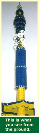
The bottom part of the real tower is rarely seen as it is surrounded by buildings. However, if you get up close, you will see that the tower sits on a circular concrete column and is attached to the adjacent building by a concrete collar.
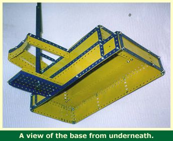
My model building is a simple box made of flexible plates and angle girders. Construction is clear from the photographs. I have simplified the actual building as I do not think that this is the most important part of the model.You may want to make it more like the original.
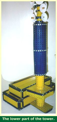
The tower sits on a base consisting of a 5 1/2 x 2 1/2 inch flanged plate with a 5 1/2 x 3 1/2 flat plate bolted on top. The column of angle girders which suppor the tower are bolted to the middle of this plate with angle brackets (see later). The bottom of the tower is a boiler bolted to the base plates.
At the collar level (just above the lower boiler), the angle girder column is attached to the building by a 2 1/2 inch double bent strip with a 5 1/2 x 2 1/2 flat plate bolted on top. This gives the column the necessary support and prevents it from swaying. The rest of the collar is made up of flexible plates and strips and does not support the tower in any way. A second boiler is bolted above the collar to form the rest of the tower base.
This part of the model consists of a cylinder made from 19 12 1/2 inch strips bolted to 3 19 hole strips which have been bent into circles and joined with obtuse angle brackets (a bit flattened).
The central column consists of 3 cylinders bolted together with a narrow strip inside. This is then slipped over the central column of angle girders and bolted in place. The galleries themselves are made of narrow strips bent into circles with floors made up of stepped curved strips. The aerials are made of conical plates or the middle bits of those old road wheels that the lugs always break off.
If you look at the real tower, you will see that the aerial galleries are a really complicated part of the building and I hav very much simplified this part of the model. Also the aerials I have used are a bit too big for this scale,but they look OK and you have to remember that the aerials are constantly being changed by BT, so the look of this part of the real tower is not actually fixed.
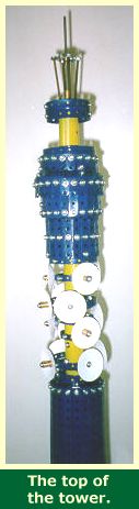
The top bit of the model is the most complicated. It is built round a 12 inch axle rod which slots into two long couplings mounted on the top of the angle girder supports. This allows the top part of the model to be lifted off for storage and transport. The top of this rod protrudes above the top of the tower and is extended with a coupling and another 5 inch axle rod to form the aerial on top of the tower.
This is a good time to get your bending machine out as this part of the model is made up of vertical strips bolted to other strips which have been bent into circles. I use a G.W. Models bending machine which is ideal. Each section is bolted to a 5 1/2 inch pulley and fitted over the central rod.
The bottom section comprises 19 5 hole strips and is fixed to the central rod. The next section up is the revolving restaurant and is made of a circle of 23 3 hole strips. In this case, the large pulley is free to turn on the central rod and is held in place by collars. There is no motor in my model, but you could fit a small one inside if you wanted the restaurant to go round all the time.
Above the restaurant is a section made of 25 fishplates and 25 obtuse angle brackets, and above this a further circle of 21 fishplates. These top two sections are bolted together with 4 obtuse angle brackets to form a single unit which is then mounted on 2 5 1/2 inch pulleys, the upper of which forms the roof. These pulleys are fixed to the central rod. Above this is a 19 hole strip bent into a circle so it is a tight fit round the rim of the top pulley. Friction holds it in.
The roof of the tower consists of an old road wheel which has lost its central conical disc. This is trapped between a sandwich of two 16 hole strips (made up of a 15 hole and a 5 hole strip overlapping) bent into circles and held together by fishplates. A bush wheel sits on top with its boss through the central hole in the road wheel. This whole part is then pressed down on top of a cylinder which is held in place by friction and is spaced out from the central rod by the heads of 4 bolts in the large pulley below.
The aerial is made from 4 screwed rods mounted onto 3 hole narrow strips which are fixed to the central rod by collars.
I painted all of the fishplates and obtuse angle brackets blue to make them match the rest of the model.
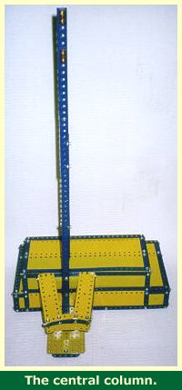
The model is supported on a column made of 6 12 1/2 inch angle girders overlapping so that they just extend up to the top of the aerial galleries. All of the lower parts of the model are bolted to these girders using long bolts and nuts to space them correctly. It is a bit fiddly getting the nuts into place inside the tower and I had to use narrow pliers for this.
I assembled the model from the bottom up adding the various modules as I worked upwards.
I hope you like my model. If you would like to see other models or would like more information about my model making and other activites, visit my website at http://www.btinternet.com/~n.pope/.
All Meccano modelers are welcome to make the model and to take copies of these instructions for their own use. However, please ask for my permission before copying into any other publication (see my website for contact details, or email Chris Bourne who will forward your request).
Nigel Pope
December 1998
HTML web page plus illustrations (bthtml.zip, 161K)
Select the link to download the file "bthtml.zip". Save the ZIP file in a new directory, and use your favourite "unzip" program to extract the files, then open the file "index.htm" in your browser to view this web page offline. The download page has been set to black text on a white background to make printing easier.
Text file plus the image files (bttxt.zip, 160K)
Select the link to download the file "bttxt.zip", which contains a single text file (bttower.txt) plus the image files containing the illustrations used in these pages. Save the ZIP file in a new directory and use your favourite "unzip" program to extract the files. You can then print out the text file which contains the model notes, and view/print the images using your browser or your favourite graphics program.
These instructions and the accompanying pictures are copyright material (belonging to Nigel Pope), and all rights are reserved. They are made freely available to Meccano modellers on condition that they are not copied and distributed in any form for sale, whether or not the sale is for profit or merely 'at cost'. Nor may they be distributed in incomplete form. Printed copies may however be made freely for personal use.