A "Table Only" Meccanograph
by Nigel Pope

by Nigel Pope
(Note: Click on any of the photographs to view the original, full size image.)
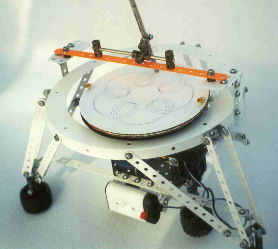
A Meccanograph is a pattern drawing machine. At any Meccano exhibition you are bound to see one. Visitors watch spellbound as with strange mechanical movements a pattern appears on the paper. Most of these machines use a rotating table which carries the paper and a moving pen which describes the pattern. My machine is a bit different. What I wanted was a Meccanograph in which the pen is fixed and the pattern is produced by complex movements of the table alone. This machine does just that. With a few standard gears and a simple motor, it produces a pattern of the type you see in the picture.
Before you start to build this machine, I should point out that because only the table moves, the types of pattern produced are a bit limited. However, by using different coloured pens starting at different points on the paper you can get quite a range of effects.
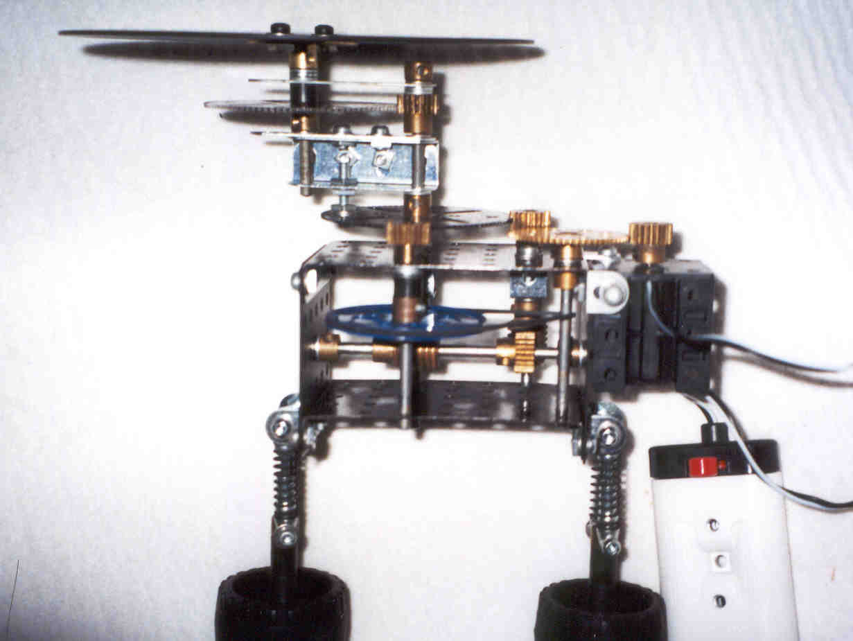
I am sure that Meccano enthusiasts will have spotted that the model looks very much like a Space Base set. This is no surprise as I used parts from a Space Base set to make it. The model is actually in two parts. The outer white bit with the big flanged ring is just a bit of the space base and is there only to support the pen and to hold the table in place. This is not a critical part of the model and I suggest you use any convenient parts you have to make up your own support. The key is to hold the pen in a fixed place above the rotating table.
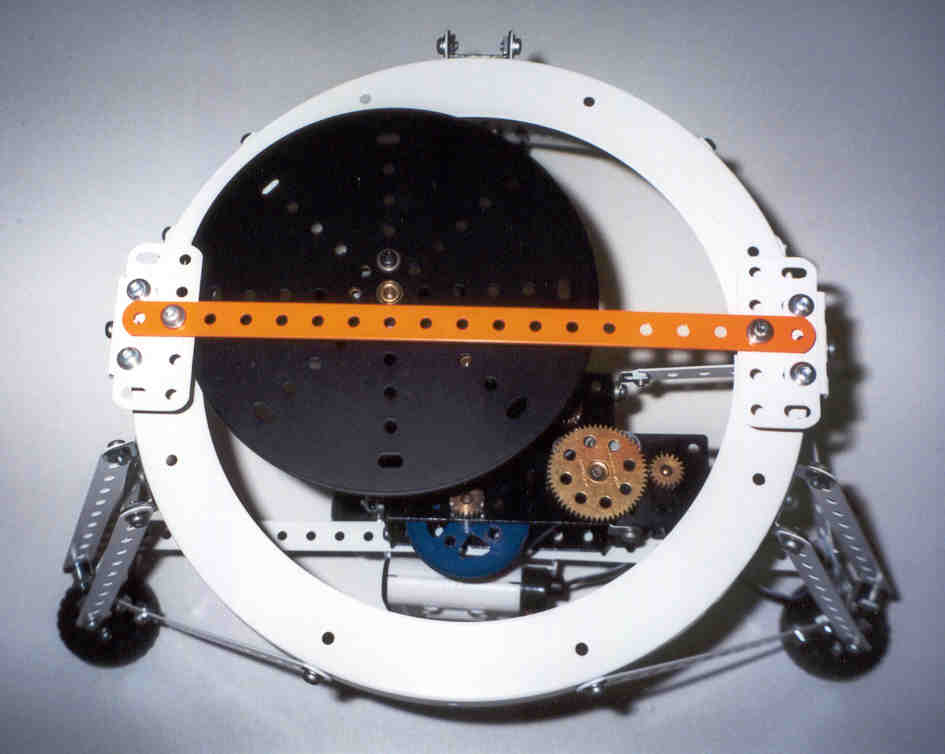
This top view, with the pen removed, shows you the table and the interesting bit which is the mechanism underneath. The table performs complex swinging movements within the full circle of the large flanged ring to allow the pen the draw the pattern. The pen is mounted on the orange strip. I will now describe how the pattern drawing mechanism works.
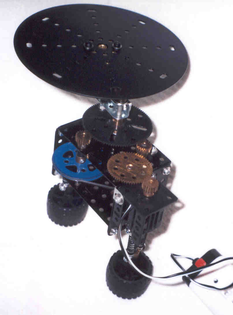
The mechanism is mounted on a simple box frame consisting of 2 flanged plates, 5 holes deep and 7 holes wide. They are spaced 4 holes apart by two flat plates 5 holes square. A 3V French motor is mounted on one side and is held on by an angle bracket at the front and a fishplate on top. The motor has a 19 tooth pinion on its output shaft and this drives a 57 tooth gear mounted on top of a vertical rod which passes through the two flanged plates and which is held in place by a collar underneath. There are no other gears on this rod.
A rubber drive belt passes round the vertical rod and then round a 2 inch pulley mounted on a second vertical rod which also passes through the two plates. This rod has a 19 tooth pinion on the top and no other gears.
The 19 tooth pinion on top of the second vertical rod engages with a 95 tooth gear which is free to turn on a third vertical rod which passes through both flanged plates. This rod extends above the 95 tooth gear and passes through the end holes of two 2 inch angle girders bolted together to form a channel section. The channel section is also free to turn on the rod. The rod now has a 19 tooth pinion fixed to it above the channel section and above this it passes through the end hole of a 2.5 inch strip which is free to turn, and the rod ends in a fixed collar.
The other end of the channel section has a short vertical rod with the table on top. The table is a 6 inch circular plate bolted to a bush wheel. The short rod is bolted to the bush wheel just above the 4th hole of the 2.5 inch strip. Below this is a black plastic collar, a second 95 tooth gear fixed to the rod and then the channel section. The channel section is bolted to the lower 95 tooth gear by a bolt which passes vertically through one of the outer holes of the gear. Suitably spaced nuts ensure the channel section is level.
The lower 95 tooth gear also drives a 19 tooth pinion mounted on top of a 4th vertical rod which passes through both flanged plates. This rod has a worm gear mounted on it between the flanged plates and this worm drives a 19 tooth pinion mounted on a cross shaft passing horizontally through the middle holes of the side plates. To the left of the cross shaft there is another worm gear which drives a 19 tooth pinion fixed to the the 3rd (long) vertical shaft. This completes the mechanism.
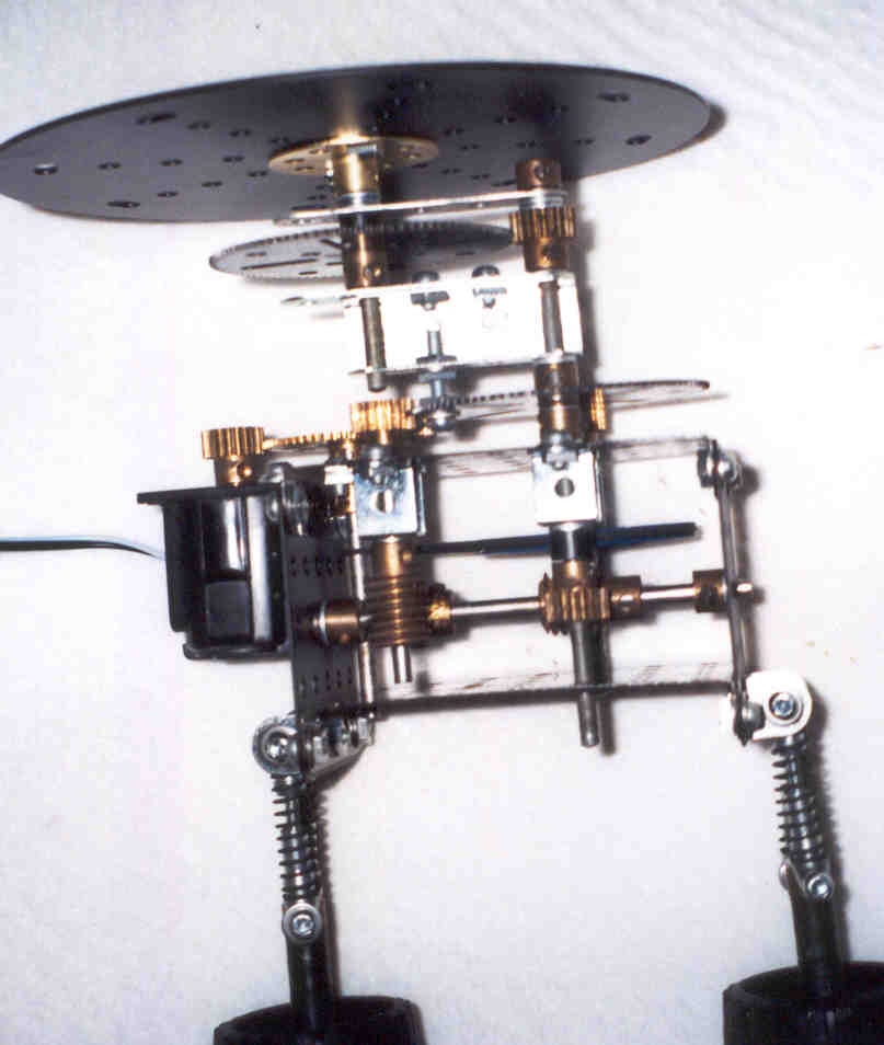
That's it. Not a complex thing to make at all. The spring suspension is just there to match the rest of the Space Base and the rubber tyres for feet keep the noise down.
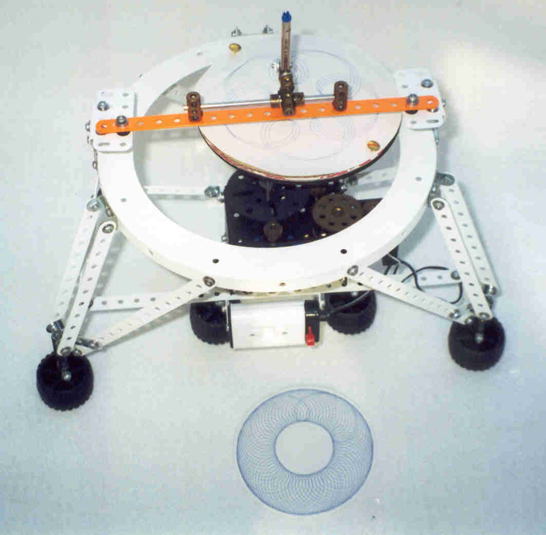
You will see that when the motor is switched on, the table is driven by two movements. A fast movement swings the table round on the end of the channel section driven by the pulley drive to the lower 95 tooth gear. A much slower motion turns the table on its own axis driven via the reduction gearing on the cross shaft. The end result is that the table whirls about while the fixed pen describes a complex lobed line which gradually resolves itself into a pattern.
The pen can be moved in position and the process repeated. Different colours add to the effect.
Of course, you could go on to add a mechanism which also moves the pen as well if you want a more complex pattern to result. However, this would defeat the object of being a "table only" system. A better way would be to introduce a variable ratio gearbox into the drive between the 2nd and 4th vertical rods. This would increase the pattern drawing options. Perhaps I will do this one day. For now, sit back and watch the pattern unfold.
I hope you like my model. If you would like to see other models or would like more information about my model making and other activites, visit my website at http://www.btinternet.com/~n.pope/.
All Meccano modelers are welcome to make the model and to take copies of these instructions for their own use. However, please do not sell copies or reproduce the plans elsewhere without my permission (see my website for contact details, or email Chris Bourne who will forward your request).
Nigel Pope
January 2001
HTML web page plus illustrations (grhtml.zip, 196K)
Select the link to download the file "grhtml.zip". Save the ZIP file in a new directory, and use your favourite "unzip" program to extract the files, then open the file "index.htm" in your browser to view this web page offline. This version has been set to black text on a white background to make printing easier.
Text file plus the image files (grtext.zip, 191K)
Select the link to download the file "grtext.zip", which contains a single text file (grtext.txt) plus the image files containing the illustrations used in these pages. Save the ZIP file in a new directory and use your favourite "unzip" program to extract the files. You can then print out the text file which contains the model notes, and view/print the images using your browser or your favourite graphics program.
These instructions and the accompanying pictures are copyright material (belonging to Nigel Pope), and all rights are reserved. They are made freely available to Meccano modellers on condition that they are not copied and distributed in any form for sale, whether or not the sale is for profit or merely 'at cost'. Nor may they be distributed in incomplete form. Printed copies may however be made freely for personal use.