
There are currently five parts to the rig electrical system:
1) Ignition
The ignition box contains an inverter, storage capacitor and trigger circuit. The inverter charges the 1uF storage capacitor to 2kV. The energy stored in this capacitor is discharged into the spark plug gap by triggering the spark plug gap into conduction using a small trigger transformer, much like a strobe lamp.
The discharge energy is about 2 Joules, and produces a very impressive spark. The image below doesn't convey the loud bang produced by the discharge !
Once combustion is established, the ignition is turned off.
2) Tachometer
The turbo shaft speed is measured optically. A probe consisting of two optical fibres encapsulated in a metal sleeve, is located about 4mm away from the nut which hold the compressor impeller onto the turbine shaft.
One fibre carries light from an intense IR light source in the tacho box. This light strikes the compressor nut, half of which is painted matt black, and half matt white. The camera also detects the IR, but displays it as green!
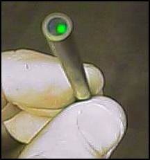
The other fibre transmits the reflected light from the compressor nut, back to the tacho box. In the tacho box, the light is converted to an electrical signal, the frequency of which is proportional to the shaft speed in revolutions per second.
The signal triggers a pulse generator, which then switches the signal to an analogue panel meter. The meter displays the average of the pulses, and is calibrated to read revolutions per minute. The current rig also has a digital counter to display rpm more accurately.
3) The Oil Pump Controller
The speed of the motor driving the oil pump is much too high for this application. The oil pressure with the 12 volt battery connected directly to the motor was more than 7 bar. Rather than re-design the mechanical mounting of the motor to incorporate some form of speed reduction, I made a simple pulse width modulated (PWM) speed controller for the motor.
There is a pressure transducer connected to the turbo oil feed, this is used as a control signal for the PWM motor controller. The required pressure can then be set, and the controller maintains this pressure as the oil heats up, by increasing the flow rate.
4) Fuel Pump Controller
The fuel pump speed control is mounted on the instrument panel. The pump speed determines the fuel pressure, and hence the fuel flow. This is used as a throttle to adjust the turbine operating speed. The fuel pump controller uses a similar PWM controller to the oil pump.
5) 'Auto starter' controller
To start the turbine, the main power switch is pressed, which activates the tacho and the front panel instruments. The oil pump must then be switched on. This starts the oil pump, which rapidly brings the oil pressure to the required level, and also applies power to the rest of the system. This makes sure I can't attempt to start the turbine before there is oil pressure.
When the 'Start' button is pressed, the ignition box and the fuel pump (which is preset manually to 3 bar) are switched on, and a relay latches. The relay holds the system in the start condition, and also connects 12V to the d.c. starter blower. With 12V connected, the starter blower provides just enough air to ensure that initial ignition takes place in the combustor.
Once ignition is detected by a thermocouple in the turbine exhaust, the ignition box is switched off, and the starter blower is connected to 48V d.c. This assists the turbine up to the speed at which it is self-sustaining. A comparator in the tacho circuit unlatches the start relay when the self-sustain rpm is achieved, and switches off the starter blower.
Other features
You can also see some pressure gauges (gages). The big one measures compressor delivery pressure (approximately), and is calibrated up to 2.5 bar (35psi). The others measure oil and fuel pressure.
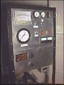
The rectangular box hanging off the bottom of the frame is the thermocouple meter for turbine inlet and exhaust gas temperature measurement.
The large analog meter is for rpm, along with the digital counter at the bottom. Battery voltage and current is displayed on the two small analog meters on the bottom right.
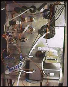
Various knobs and switches for ignition, fuel and oil control. On the back of the panel are the various controllers, neatly wired as you will note :-) and the 10Ahr lead acid battery.