
The rig is now basically at the point where it can be considered 'turnkey', so the second objective has been met (the first objective was to get it to self-sustain).
Power take-off
The next major objective is to add a power turbine and reduction gearbox to the basic turnkey 'gas generator'.
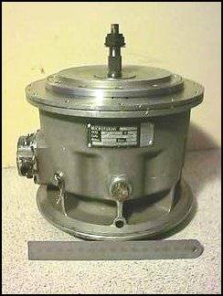
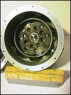
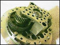
The plan is to couple a larger turbine, probably the turbine from the Indycar turbocharger I have, to a very nice 10:1 epicyclic reduction gearbox I recently acquired. This gearbox was originally part of an air-powered starter motor for RR Adour turbojets used in British Aerospace Hawks and Jaguars.
The gearbox is shown here with the obligatory 150mm rule for scale purposes.
A significant difficulty with this part of the project is coupling the power turbine and gearbox together. The power developed by the power turbine (probably around 6kW) is not in itself difficult to handle, but the coupling must be able to cope with the radial and axial misalignment that is inevitable between the two, at shaft speeds of up to 50krpm. Currently I am looking at a dual membrane coupler, which will need to be dynamically balanced.
Combustor developments
A common problem with gas turbines running on liquid fuel is achieving acceptable fuel atomisation over the full fuel flow range required (this is due to the square-law nature of the flow characteristics with pressure of atomising nozzles). This can be overcome by a number of means, including dual or duplex nozzles, supplementary air atomisation at low fuel flows, gas ignition and fuel vapourisation.
The latter technique is widely employed in many gas turbines. The liquid fuel is vapourised by passing it through tubes inside the combustor. In this vapourised state it burns more cleanly, and fuel delivery is simplified. Much less pressure variation is required to deliver the full fuel flow range.
Chris Bennett suggested a hybrid fuelling scheme with a low flow-rate (~0.3gph) domestic boiler atomising nozzle operated at its rated pressure for starting, supplemented with a vapouriser for normal operation.
Based on this suggestion, I modified the combustor liner to provide vapouriser fuel delivery. Three 6mm stainless steel tubes bent at right angles have been welded into the liner, so that they convey air from the outside of the liner to the core of the swirler vortex in the primary zone.
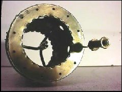
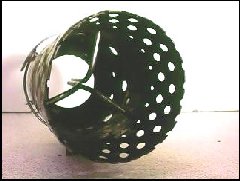
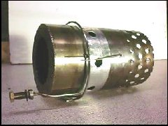
A stainless steel fuel rail is fitted around the liner. Brazed to this are three copper feed pipes. Into the ends of the feed pipes are brazed 0.8mm diameter stainless steel tubes. The 0.8mm tubes are bent at right angles, and enter the open ends of the vapouriser tubes, acting as delivery nozzles for the fuel.
Fuel delivery is to be regulated by a PWM injector from the existing atomiser fuel system. The idea is to fix the fuel pump speed to give 7 bar for the atomiser nozzle. As the vapouriser system needle valve is opened, fuel delivery will increase, so the atomiser pressure will drop. Initial tests on the vapouriser suggest that at least 10usg per hour fuel flow is available at less than 5 bar. Some work needs to be done to balance the two deliveries.
(This fuel delivery system has not been tested as of 4th October 98)
Nor has it been tested as of February 21st 1999 !! I'm waiting for the weather to improve !!