
These optional components (Main motor, Head end motor, Main generator, Head end generator, Air compressors and Power distribution board) can be left off the model if you so desire or do not plan to show the model with the top removed.
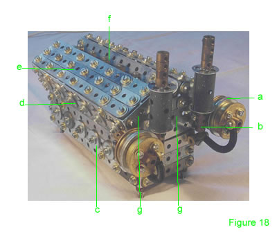 The turbos and exhausts are constructed by bolting a stack of five 1" thin strips to a hole in a flanged wheel on the bossed side. Clamp another flanged wheel face to face with a 1½" rod spaced by three 6-hole wheel disks (Fig 18a). On the other side of the 1½" rod, bolt on a short coupling. This coupling is used to bolt the assembly to the motor. On the other hole of the 1" thin strips, bolt a coupling (Fig 18b). The coupling carries a 3" rod with a large washer, sleeve piece, large washer and four collars on the end. Bolt a tension spring to the boss of the outer wheel flange and the other end to a threaded boss on the motor.
The top half of the motor is constructed by bolting 1½" angle girders to three composite 6½" strips in parallel (Fig 18d).
Bolt 1½" strips across the ends of another 3 composite 6½" strips (Fig 18e). Bolt this at right angle to the other three composite strips you have just made using angle brackets.
This forms one of the head banks of the motor.
Make another head bank as above.
Bolt the head banks to the bottom half of the motor using obtuse angle brackets.
The top middle of the motor is made up from a U girder made up of composite 6½" strips and obtuse angle brackets. This joins the two banks together along the middle. Along the top of the middle strip, bolt 6 collars (Fig 18f) at equal distances.
The ends of the banks are filled in using 1½" strips, 3 ½" and 3" strips (Fig 18g).Along the middle strip of the top half, bolt two ¾" washers at equal distances to form a row of six (Fig 18d).
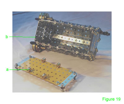 The bottom half of the motor is constructed by bolting 1½" angle girders to three 2½" strips in parallel. This forms the ends (Fig 19b). Join the ends with 5½" strips extended by 2 holes with 2½" strips to form a 2½" by 6½" rectangle. Along the middle 6½" strip, bolt two ¾" washers every 1" to form a row of 6 equally spaced ports (Fig 18c). This simulates the access ports on the real motor.
The base of the motor is made up with a 5½" x 2½" plate with 2½" flat girders bolted to the ends. ¾" bolts on all four corners hold collars as mounts. Four threaded collars (Fig 19a) are bolted flat to the 5½" x 2½" plate so that the top half of the motor can be bolted to it.
Bolt the turbo's on using the short couplings and then bolt on the bottom using the threaded bosses (Fig 19a).
(Original design by Chris Bourne)
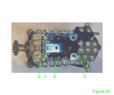 Bolt a 3½" flat girder (Fig 20a) to a 1" angle girder. Do the same for the other side and join them with a 1½" flat girder (Fig 20b). Bolt another 1½" flat girder below the 1½" end flat girder (Fig 20c).
Bolt a 15/16" threaded pin in the center of the 1½" flat girders. Tighten a ¾" flange wheel, 2 collars and a 14T sprocket to the pin.
At the other end of the 3½" flat girder, bolt angle brackets. Bolt an 8-hole wheel disk to the lower angle brackets. Bolt a short threaded pin in the center of the 8-hole wheel disk and tighten a ¾" flanged wheel to it with the flange flush.
Using obtuse angle brackets, bolt two 1½" flat girders (Fig 20d) to form a sump.
Using angle brackets, and three 3½" strips, form a U girder and bolt it to the 8-hole disk and top hole of the 1½" flat girder to form the valley in the motor.
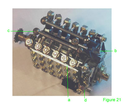 Using 11/8" bolts, bolt two plastic collars, three washers and a collar to a 3½" strip Fig 21a). Do this to the first six holes. In the seventh hole, secure a rod and strip connector on a bolt (Fig 21b). Place handrail supports (Fig 21c) into the first and sixth collars spaced with small spacers. Place 3/8" bolts into the rest of the collars and run a 3" rod through the handrail supports. Bolt this assembly to the 3½" flat girder with obtuse angle brackets. Do the same for the other side. Neaten up the ends with angle brackets to hide any gaps. Run plastic tubing from the ends of the 3" rods into threaded collars (Fig 21d) bolted to the sides of the motor. This simulates fuel lines etc.
 Four 2½" x 2½" flat plates are bolted into a square using angle brackets.
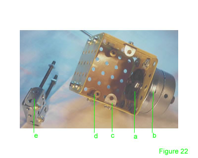
Against one plate, bolt in the middle a bush wheel (Fig 22a) boss facing inwards. On the outside using the same bolts, bolt two 8-hole wheel disks and a wheel flange (Fig 22b), flange facing outwards.
Slide two boiler ends onto the rod into the wheel flange, slide two collars onto the end of the rod and tighten the outer collar to the rod.
Using angle brackets (Fig 22c), bolt the unit to the floor of the chassis. Bolt threaded collars (Fig 22d) to the top inside holes of the side plates, and bolt the top 2½" x 2½" plate to the threaded collar.
Bolt 1" girders (Fig 22e) to the end of a 1½" flat girder. 2½" threaded rods lock nut onto a 1½" girder. Across the top bolt another 1½" girder to the 1½" flat girder.
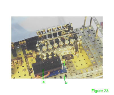 Pass a ½" bolt through a centre hole of p#216 (Fig 23a) and tighten a nut onto the outside. This is to bolt the generator to the chassis.
Pass a threaded rod adapter though an 8-hole disk and tighten a 14T sprocket to the outside.
Tighten a 2½" threaded rod into the threaded rod adaptor and pass the rod through the boiler and through another 8-hole disk. Tighten a threaded boss (Fig 23b) to the other side to clamp the disks together against the boiler.
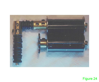 Bolt two sleeve pieces together. For the lower sleeve, pass a 1½" bolt through a large washer into a threaded rod adaptor. Pass the adaptor through a large washer and clamp a 14T sprocket on the other end.
For the top sleeve, do the same except clamp a short coupling to the end. A 1" rod leads into another short coupling at right angles holding a 1½" rod. Use washers as spacers or the new rubber collars.
INTRODUCTION | PARTS LIST
CONSTRUCTION: Bogies & Chassis | Bumpers & Undercarriage | Cabin & Body | Roof & Fans | Optional Components | Mounting the Components & The Track
© Chris Els January 2003, cels@webmail.co.za
"The Meccano Model Library" is owned and run by Chris Bourne, cfpb@lineone.net
Website designed and maintained by Donna Smillie, dms@zetnet.co.uk
http://www.users.zetnet.co.uk/dms/meccano/loco/const05.htm