
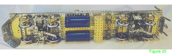
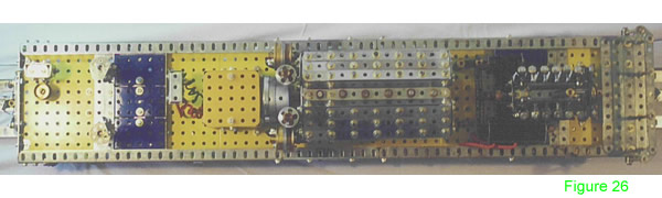
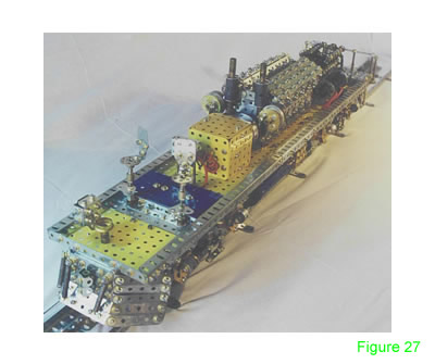
The following pictures show how the head end motor, main motor, fuel tanks etc are mounted to the chassis.
 Stack up three 5½" strips as the sleepers. Face two angle girders towards each other and bolt them six holes apart using the slotted holes.
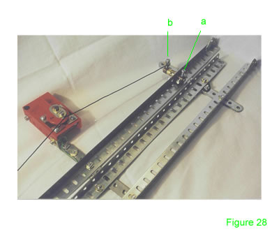
The center pickup rail is insulated using insulating fishplates, offset at an angle. The pickups run along the top of the rail for current.
The switch actuators are 1" rods journaled in a double arm crank bolted to the side of the track.
Using collars and long bolts, adjust so as the switch actuator on the bogie hits the long bolt (Fig 28a), the string attached to the outer long bolts (Fig 28b) pulls the electrical switch to reverse, the switch actuator on the other side of the truck is pulled in the opposite direction, ready to pull the electrical switch into reverse when the train reaches the other side.
This way the Loco will run back and forth unattended. It was tricky to set up, but once done it was surprisingly reliable.
Another idea might be to use the light sensitive Photo cell (E602) at each end of the track and a relay (E606) from the Electronic parts range.
INTRODUCTION | PARTS LIST
CONSTRUCTION: Bogies & Chassis | Bumpers & Undercarriage | Cabin & Body | Roof & Fans | Optional Components | Mounting the Components & The Track
© Chris Els January 2003, cels@webmail.co.za
"The Meccano Model Library" is owned and run by Chris Bourne, cfpb@lineone.net
Website designed and maintained by Donna Smillie, dms@zetnet.co.uk
http://www.users.zetnet.co.uk/dms/meccano/loco/const06.htm