
(AKA The Combustor)

(AKA The Combustor)
"How do I go about building a combustor ?"
The first part of the answer is to understand what a gas turbine combustor does, and how it differs from the combustion chamber of a piston engine.
In a piston engine, the fuel-air mixture is adjusted so that complete combustion of the fuel takes place (stoichiometric ratio). This would be typically be 14:1 air/fuel. The resulting temperature rise in the gas may be 1500C or more. However, since the combustion duration is very short, and heat is conducted away very rapidly from the associated engine parts, the working temperature can be controlled to within the material limits.
The fundamental difference in a gas turbine combustor is that combustion is a continuous process. Fuel must still be burnt at the correct air-fuel ratio of 14:1, but there are no practical turbine or combustor materials that will withstand 1500C plus continuously.
This problem is neatly solved by splitting the air from the compressor into two (or more) streams. The primary stream is used to burn the fuel at the stoichiometric ratio, and the secondary stream is then mixed with the high temperature combustion products from the primary stream (this is referred to as dilution). The result is complete combustion of the fuel, and the entire mass of compressed air heated evenly to the design operating temperature of the turbine.
That's the first part of the answer. The second part is much easier - you copy someone else's design !
Billions of currency units all over the world have been spent developing designs for combustors, all you have to do is understand the principle outlined above, find a design of combustor (there are several commercial ones on this and other webpages), scale it to suit your turbine size, and adapt the construction to suit your available resources.
So...........
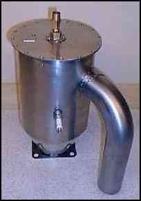
This is the original combustion chamber I used. It is designed for the release of huge amounts of heat energy, far more than my turbocharger gas turbine is likely to need ! I used it because I lacked the facilities to manufacture my own. This turned out to be a good move, because this is probably the single most difficult part of a gas turbine to build successfully.
It is off an old (1976) Rolls-Royce Dart turboshaft aero engine. The Dart has a lot of these fitted around the engine. (Rolls-Royce kindly donated this to the project, belated thanks !)
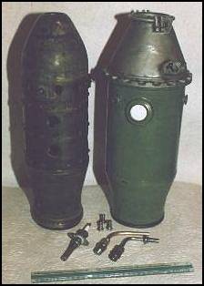
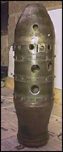
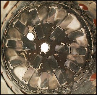
The combustion chamber consists of two shells, the inner one (on the left of the left-hand image) the flame tube or liner, and the outer one, the housing. The right-hand image shows a clearer view of the liner.
The housing has a diffuser bolted to the top, which de-accelerates the incoming air from the compressor, and increases its pressure. The diffuser also holds the spark plug (lower hole) and the fuel injector (smaller hole at the top of the diffuser).
The liner, made of heat resisting steel, delivers the air from the compressor in the correct proportions to the fuel injector for complete combustion of the fuel, and to the dilution zone in the combustion chamber to ensure that the turbine design operating temperature is not exceeded.
This is achieved by careful balance of the size and position of the air delivery holes in the liner.
At the bottom of the left-hand image you can see the spark plug (left), and the two fuel injectors. The righthand one is the original kerosine injector. I used propane in my rig originally, because it doesn't require a pump, and is easy to ignite. This is delivered via an adjustable bi-conical nozzle (middle) I designed and had made by a friend at work (Thanks Ernie !)
Here are views of the two ends of the liner. On the left is the air inlet end, and the swirl vanes are clearly visible. On the right is the exhaust end, the swirl vanes are just about visible at the far end. You can see some of the wall cooling rings inside the liner, and the spark plug aperture near the swirl vanes.

The disadvantage of propane is that it is far more dangerous than the most widely used turbine fuel, a type of kerosine. A word of warning: it would be EXTREMELY DANGEROUS to use neat gasoline as fuel!
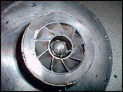
This is the combustor liner from an Allison 250 turboshaft (there is only one combustor in this design). This engine, rated at around 400shp/300kW, is (probably) the most successful helicopter engine in the Solar System ! This gives you an idea of scaling. This combustor is around 150mm diameter and 250mm long.
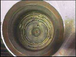
I particularly like the simple method of introducing swirl into the primary air, using pressed flat flaps in the primary zone. This is (not very clearly) illustrated in the right-hand image, which shows a view taken of the primary zone taken from the exhaust end.
Home-made combustor development
One of the aims of the project was to make a more compact liquid fuelled combustion chamber. This proved to be particularly difficult.
There are quite stringent requirements of the design to get the correct air-fuel mixture for reliable ignition, stable, efficient combustion and acceptable turbine inlet temperatures. However, there is no easy way to calculate the size, number and location of the various combustion chamber liner air distribution holes, or the shape and size of the chamber itself.
There are really two ways to arrive at a design - by trial and error with some intuition and research, or with an expensive and daunting fluid dynamics simulator. As a home builder, the second option is not really an option ! The first option requires a lot of patience and experimentation.
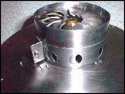
I haven't fully developed this combustor yet. There are a number of shortcomings in the design, but these will be addressed eventually. The combustor, shown below, is about 300mm long overall, and 150mm in diameter. The exhaust cone has a rather steep angle, but this keeps the combustor compact. It was fabricated from 18g stainless steel. In hindsight, it is too large for the application.
Compressor air is fed into the combustor tangentially, via the delivery duct on the side. I now know this to be a very bad design feature. It creates a very asymmetric flame, pushing the combustion on to the liner wall. The compressor delivery should ideally be axial to the combustor (like the Dart combustor), or if this takes up too much room, then it should be straight radial. When I redesign the combustor, I expect to eliminate the tangential air inlet.
The 'cool' end is sealed by a cover plate which is fastened to a flange on the end of the outer casing. This cover plate carries the fuel connector flange, and a small removable access plate, which allows adjustment of the burner air-fuel ratio (during operation if required). The fuel connector flange can be removed from the cover plate (definately NOT during operation !) to allow the burner nozzle to be changed, without having to dismantle the combustor. The fuels to be used include paraffin, kerosine and agricultural diesel, since all are readily available within a few metres of my workshop.
The image also shows the position of the spark plug. This position was chosen to intercept the spray of fuel from the burner nozzle. This is also now known to be a poor design feature. The spark plug should be located where the fuel-air mixture is correct for ignition, closer to the fuel nozzle. The spark plug is cooled in operation by a flow of air around the threaded portion.
During design of the combustor, I thought about various ways of atomising the fuel to allow ignition to be acheived readily using a spark plug. I tried automotive injectors at various fuel pressures, but they give a rather high flow rates at fuel pressures where atomisation was acceptable. I thought about vapouriser tubes, and quite like the idea still, but this involves starting the turbine using propane or petrol - which is something I would like to avoid.
(Update October '98 - See Testing and development for news on the development of vapouriser-based fuel delivery)
I decided to use a domestic central heater burner atomiser nozzle, which has been used succesfully by a few other builders. These are reliably ignited by an electric spark.
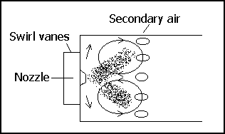
The fuel nozzle (the brass part in the centre) is surrounded by a set of swirl vanes, mounted in the burner tube. Around the burner tube is the primary air adjustment band.
In my burner, the combustion air is delivered radially to the burner tube, and the airflow can be adjusted by rotating the perforated metal band around the burner tube. The metal band (shown in the right-hand image) can be adjusted during operation, by removing the access panel on the combustor cover plate.
The swirl vanes create a vortex in the vicinity of the nozzle, to stabilize the flame. This part of the design is a straight crib from the Dart combustor.
These sketches give some idea of the vortex generation, and how the fuel-air mixture is re-circulated in the primary zone, to give more time for combustion to occur.
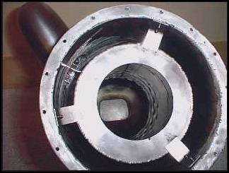
The view below shows the cool end of the combustor, with the cover plate removed. The combustion liner is pushed in place axially against the exhaust nozzle by the three spring tabs. It is located radially by the burner tube, which is a close fit into the hole in the back of the liner.
It is not very clear, but looking down the liner, it is possible to observe the dilution holes, and the exhaust aperture. Between the liner and the outer casing, at the point where the compressor delivery duct enters, it is just possible to see the flow separator I fitted to offset the effect of the tangential air flow introduced by the compressor delivery duct (More about tangential air delivery later).
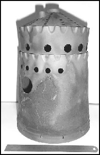
The combustor liner is shown below (The 150mm rule shows the scale). The burner tube fits into the large aperture at the cool end of the liner.
Secondary air is admitted through a series of holes around the periphery of the liner. In this photo, this has not yet been done. After some experimentation, eight 10mm holes were drilled around the liner, about half way down its length. Initially, there were a series of slots (visible in the image), but it was impossible to get enough secondary air for complete combustion.
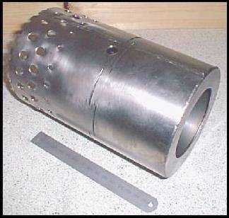
The access hole for the spark plug tip is visible near the slots. Some air leaks around the plug tip to provide cooling for it.
Dilution air is admitted throught the subsequent rows of larger holes toward the hot end of the liner. These holes have been partially swaged in the direction of air flow. The last set of 'half-holes' are actually formed in the edge of the liner, so that cool air is available for the walls of the exhaust nozzle.
If there are any developments to the combustor, they will be in the Testing and development section.
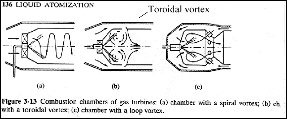
Click these buttons if you would like to see some engineering cutaways of combustion chambers.
 Cutaway showing components of combustor (39k)
 Cutaway showing air and flame distribution (27k)
(click the back button on your browser, when you have seen the images, to return here)