

(It eventually stopped raining long enough to get it started for the first time ! Scroll to end of page)
The Microturbo Air Producer is a small single shaft gas turbine engine. There is no external shaft output, instead, the two stage axial turbine drives an oversize radial compressor. The output of the compressor is split, and around one third of the mass flow is bled off. This drives a 'cold' air turbine, which is attached to a gearbox connected to the aircraft's main engine to effect starting. (The gearbox is the one shown on the Testing and development section of the DIY turbo turbine page.)
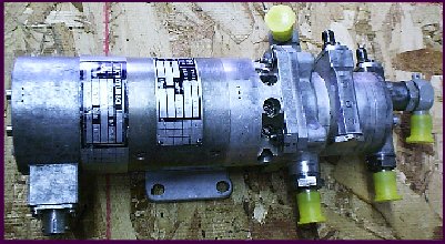
The bad news is that the Microturbo was in pretty poor condition, as can be seen ! It has suffered from water damage, and I have a feeling that the unit may have been recovered from a damaged airframe. However, it is a fine piece, and it deserves careful restoration. The turbine 'core', i.e the compressor impeller, main bearings and two stage turbine appear to have survived untouched.
Here the unit has been stripped down as far as is possible, all the pieces cleaned and refinished, new exhaust duct (as yet untrimmed) and new fuel fittings installed.
As normal there was no starter. So, like for the Lucas APU, this part has been adapted from a motorcycle starter. It is mounted on the flange at the compressor end, and, unlike the Lucas GTS, continues to rotate with the turbine shaft during operation. Since the rotor/starter reduction ratio is only 2:1, the starter needs to be rated continuously to 25krpm. This requires that the commutator and windings are reinforced (Kevlar and epoxy), and that the rotating assembly is dynamically balanced.
Some of the oil fittings were also missing, and have been replaced using commercially available Metric Parker-Hannefin parts.
Thanks to Lee Palmer's keen eyes, a couple of extremely weather beaten Microturbo test stands came to light during a trip to an aircraft dismantlers, providing the essential parts of both the fuel and lubrication systems for this turbine. Thanks Lee, for spotting them !
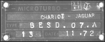
Here's the identification label off one of the units:
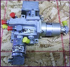
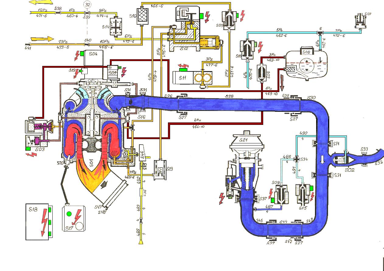
The fuel and oil system consist of an electric combined fuel and oil pump, and a electrically operated spill valve for controlling fuel delivery to the burners.
Oil is stored in the frame mounted tank, and pumped through filters to the turbine and starter gearbox bearings. Oil pressure is maintained by a PRV in the oil pump housing. A pressure switch in the oil system illuminates a front panel lamp and releases an interlock on the starter and FSOV (fuel shut-off valve) when the oil pressure reaches the normal operating point.
Fuel is fed from an independent fuel tank via a bowl filter to the pump. Fuel pressure is maintained by a second PRV in the fuel pump housing. Fuel is fed to the burners, where the spill valve in the burner fuel return controls the percentage of fuel fed to the burners, or spilled back to the fuel tank.
The engine is to be controlled by a crude (but of course complicated !) analog controller (ECU). This provides sequenced starting, and eventually closed loop rotor speed control. A front panel control sets a %N1 value, and the feedback provided by a shaft speed sensor is compared with this setpoint, the controller automatically adjusting the fuelling to achieve and maintain the set speed (in theory, at least). The speed set point is backed off if the EGT exceeds a set temperature to provide acceleration control. The error signal from the control loop adjusts the PWM drive signal to the spill valve.
The engine controller will be run open loop (i.e.under manual control) initially in order to establish the characteristics of the system, to ensure the final closed loop controller will be stable.
The ECU is connected to a 12 channel  Picolog pc-based logger so that various parameters of the control system can be recorded during starting and running.
Here is a block diagram (173kb) of a typical Saphir installation, in this case from a Czech L29 trainer. (Courtesy of www.L39.com)
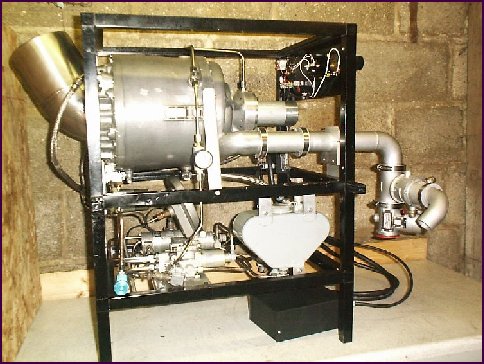
Restored engine runs for the first time ! After some careful system testing, Ian Bennett and I set up the engine on my launch pad (correction - was launch pad, is now the wife's pergola) along with the Picologger, notebook pc, numerous video cameras and, possibly the most important item, a large fire extinguisher with the safety pin removed.
With the Picologger and video cameras running, the start button was pressed, initiating an automatic start sequence. After a short delay for oil and fuel pressure to be established, the contactor closes and the ignition and starter motor are enabled. As the shaft passes the 10% N1 mark (about 5krpm) the fuel shut off valve opens, seconds later combustion is established, and the engine continues to accelerate past 40%, where the starter motor cuts out. On the first run, as a precautionary measure, the engine was shut down 5 seconds later to look at logger traces.
Due to the long combustion delay, significant quantities of fuel had accumulated during cranking, and the logged EGT trace showed an EGT peak well in excess of 600C for 3 seconds. Subsequent starts showed much reduced combustion delay, and no EGT excursions.
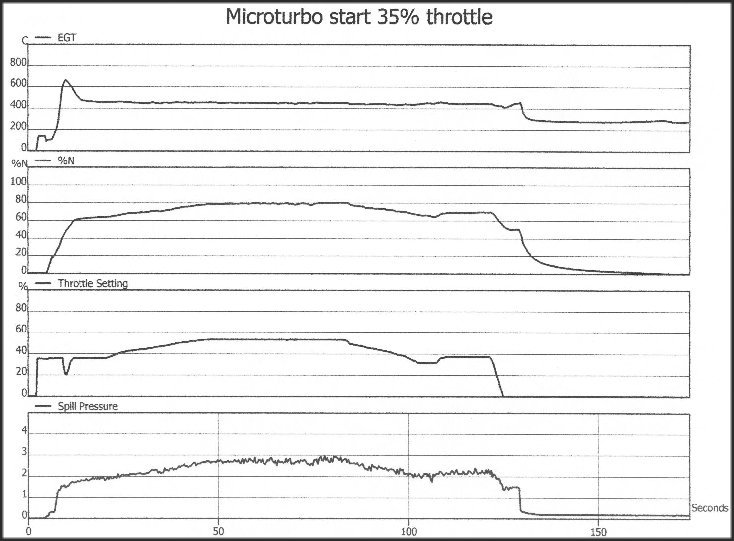
Here is a Picolog trace (69kb) of one run. It shows the EGT, % N1 shaft speed (100% N1 = 52krpm), percent throttle setting, and the pressure in the fuel spill line in bar.
At the start of the run, EGT indicates 0C until the rig is powered up. Throttle setting also jumps to 35% as power is applied. EGT jumps to 150C, since the combustor was still hot from the previous run. EGT then dips as cranking passes cooler air through. At the same time the rotor shaft accelerates from 0 to about 20%, when combustion occurs, and EGT increases to over 600C. As it passes 600C, the throttle setting is automatically backed off to about 20%, and the EGT drops back again.
Shaft speed and EGT stabilize at about 60% and 450C respectively after 15 seconds or so, then the throttle is manually wound up to 45%. The EGT actually stays fairly constant during this time, and %N increases to 80%. Sometime later the throttle is backed off, and at T+130 seconds the stop button is pressed to terminate the run.
At this stage, a lot of oil was noticed to be dripping from the starter motor, so it looks like the shaft oil seal may have failed, or that the oil pressure in the gearbox is too high due to the absence of any scavenge. However, we concluded that the tests had been pretty succesful. The engine is shatteringly noisy for such a small thing !
During the runs the bleed air from the air handling system was directed towards the exhaust end of the engine. The blast from this has to be felt to be believed, it is like a solid rod of hot metal (the compressor output is ~ 150C). The rig has no wheels fortunately, as the thrust from this output is significant, enough to cause the bleed nozzle to twist on its mounting.
Future Plans
As this engine is fitted with the airhandling accessories from the the test stands, and the plan is to use a nice air motor from a Russian Isotov helicopter engine, shown below:
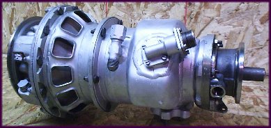
This unit consists of a single stage cold air turbine, with a nominal 10:1 reduction gearbox. The power rating of this airmotor is not known, but the Microturbo air producer is known to be capable of driving a matching Microturbo airmotor to 37kW/50shp.
I learnt a lot about this engine from an Air Publication document, kindly lent to me by Ian Bennett.
Thanks again Ian !! Ian Bennett's turbine hobby pages