
In building the model, the general sequence of these instructions should be followed.
Note: The photographs referred to in the text are mostly clear enough when printed as black and white hard copy. Some detail may be lost, however, so if you will not have access to a computer when you build the model, it might be wise to make notes about any important information which is not clear in your printout while you can still see the original image! Long bolts and washers for spacing are not mentioned in all occasions. It should be obvious when building when these are required, but not mentioned. Many long bolts were used where they were not strictly necessary, but because they are sometimes easier to use when bolting several parts together in hard to reach places.
The upper and lower wings are constructed on similar lines, but the upper wing is complicated by the aileron mechanism. I describe the construction of the wing first in terms of the general structure, and then discuss the details later on. Builders may wish to add the details as they go, to save having to disassemble parts of the wing later - as always, read the whole of the section carefully before beginning construction in order to see where these extra details occur. But it is quite possible to build the basic wing first and then add the details later, which is how the original model was built.
Two 24 1/2" girders 1 and 2 are bolted together to form a single strong U-girder. Bolt the holes of the upper girder 1 to the holes of lower girder 2, so that the plates which form the surface of the upper wing can be bolted to the slots of upper girder 1. This will allow them to be adjusted slightly as the wing is built up. The centre of the U faces forward, towards the leading edge of the wing. In the model, the centre of the U carried three bolts spaced out to hold girders 1 and 2 together before the plates were bolted to them.
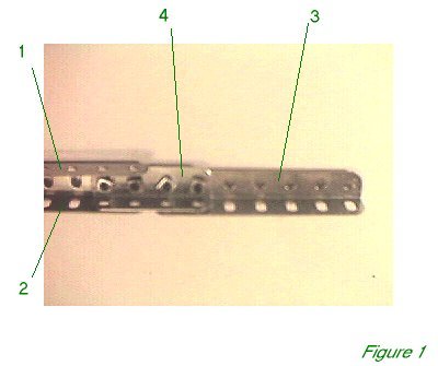
Figure 1 shows the end of the left U girder. A 3 1/2" girder 3 is butted onto the U girder using a 2" girder 4 to straddle the join. A similar girder is bolted to the right side of the U girder, giving a 31 1/2" compound girder overall. This is 1" short on either side of the full wingspan, which is therefore 33 1/2" overall.
Twenty-four 5 1/2" x 2 1/2" flexible plates are used to cover the wing - twelve on each side, six on top and six on the bottom. On the top, the outer three are bolted to the compound girder on their fifth holes, while the inner three plates are bolted to the compound girder by their fourth holes. The corresponding lower plates are still staggered in the same way, but they are bolted to the upper plates at the rear, and to the curved plates at the leading edge. This results in a half-inch space at the back of the wing for the aileron.
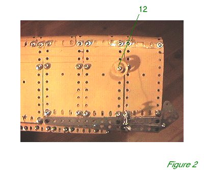
Figure 2 shows the outer part of the wing with the aileron in place. The leading edge of the wing is formed by thirteen 2 1/2" x 2 1/2" curved plates (part 199) and two 2 1/2" x 1 1/2" plates curved to a similar angle. These two smaller plates were positioned next to the end curved plate, and overlapped the next curved plate by one hole. By part numbers, from left to right, therefore, the leading edge goes: 1x199, 1x188 (1h overlap), 11 x 199 (1h overlap) 1x 188, 1x199. The U-bend of part 199 is close to that required for the leading edge but will need to be squashed a little more. Of course it is possible to use ordinary 2 1/2" square plates and bend them, or indeed curved plate part 200, and bend that, but using part 199 will cause the minimum amount of distortion to the plates.
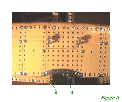
It is probably easiest to bolt the plates in place working from the centre outwards. Start by leaving 3 1/2" - 7 holes - clear in the centre of the compound girder. Figure 3 shows how the centre will eventually be filled in with 4 1/2" x 2 1/2" flat plates, but they should be left out to start with and filled in later.
At the rear, the inner plates have a 7 1/2" perforated strip between upper and lower plates to stiffen the rear edge of the wing. The outer plates are joined together using 1/2" narrow strips (part 806b). Fishplates can be used instead but the narrow strips are easier to keep completely out of the aileron as it moves.
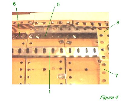
At the front, on the leading edge, leave a 2 1/2" gap in the centre where the last 2 1/2" curved flexible plate will be bolted when everything else is finished. The flexible and curved plates are bolted to perforated strips on the inside of the top and bottom of the wing. In the model a 25 1/2" strip was used in the middle with two 19 1/2" strips, one on each side of the wing, with the arrangement repeated on both top and bottom of the wing. Figure 4 shows the inner side of part of the wing where a 25 1/2" strip 5 butts against a 19 1/2" strip 6.
In Figure 4 you can also see the edges of 4 1/2" x 2 1/2" flat plates 7 and 8. These will be bolted in the centre of the wing, later, the edges pushed under the inmost flexible plates. They do not overlap each other, and in the Figure 4 it can be seen that they are at an angle to each other. The front plate is more or less horizontal, while the rear plate is angled downwards, to emulate the curve of the wing, which is smoother elsewhere with the flexible plates. A third 4 1/2" x 2 1/2" flat plate is bolted at the front of the wing on the underside, opposite plate 8. But no plate is used to correspond to plate 7 at the back of the wing, in order to allow a small bit of space for fingers when completing the final model.
Figure 3 shows the completed centre of the wing with two 4" curved strips 9 overlapped by one hole only which are bolted to the 5 1/2" x 2 1/2" plates on either side. The central 2 1/2" x 2 1/2" curved plate can be bolted on the top side, curved down and slid between perforated strip and flat plate on the bottom side. It can then be bolted in place through the centre hole at the front edge using a 1 1/4" long bolt passing all the way through.
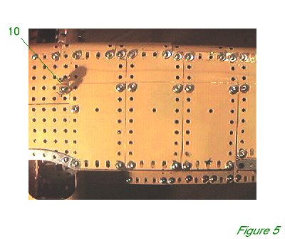 |
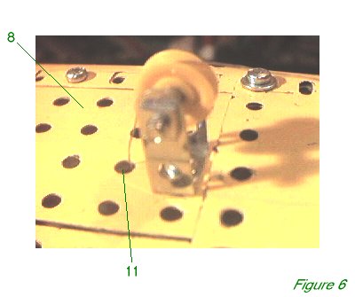
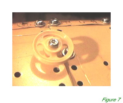
In Figure 5 you can see assembly 10 carrying the aileron wires. Assembly 10 is shown in more detail in Figure 6. A 1" x 1/2" narrow double angle bracket (part 811a) carries a 1/2" bossless pulley on a pivot bolt. The wire will come up from the fuselage through flat plate 8 (and it's opposite number below), through hole 11. The wire then continues to assembly 12 in Figure 2. Figure 7 shows assembly 12 in more detail. It is a 1" bossless pulley held by a pivot bolt. The pivot bolt passes through the pulley and a plastic spacer (part 38a) before entering the wing but a collar could be used instead. In the model I used yellow pulleys and spacers to have them blend in with the surface of the wing, so they are less obtrusive. |
 |
|
 |
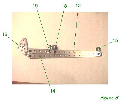 The wire continues around the pulley to the aileron. Figure 8 shows an aileron, in fact the left aileron, from above. Two 7 1/2" perforated strips 13 and 14 are bolted together at one end and to a hinge 15. Strips 13 and 14 are bolted to a 1" triangular plate at the other end and a 1 1/2" x 1 1/2" triangular plate 16 is bolted to the third hole of the 1" triangular plate.
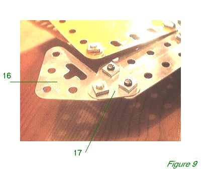 Figure 9 shows the underside of an aileron in detail, showing 1" triangular plate 17.
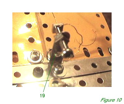 A second hinge 18 is bolted to strip 13. A 1" x 1/2" narrow angle bracket (part 812b) 19 is bolted next to hinge 18 and carries a 3/4" long bolt in the top hole, attached by a retaining nut on each side. This is shown in detail in Figure 10. The aileron wire can be wedged with a nut to the tip of the 3/4" bolt and the bolt can be finely adjusted on bracket 19 by moving the retaining nuts.
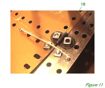 A small length of elastic is attached to a small washer or nut and fed through strip 14 opposite the bracket. It is passed through a suitable hole in the underside of the wing and tied off to a washer on the other side, so that it tends to pull the aileron down. This is shown in detail in Figure 11.
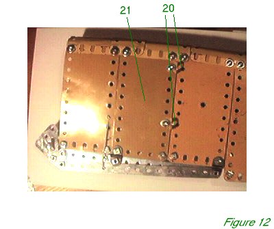 Figure 12 shows the underside of the top wing - this is the right wing, and the leading edge is to the top of the picture. Two angle brackets 20 are bolted to flexible plate 21. I used new French angle brackets as this allow me to push the hole of the bracket under the edge of the plate. I have found that old Binns Road brackets seem to be slightly shorter in this regard and the hole can't be pushed under an edge. It is useful to have the slot sticking out as it makes attaching the wing struts much easier, but the bracket can be bolted in place with the slot under the plate if necessary.
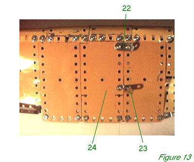 Figure 13 shows the underside of the top wing, closer to the centre. 1" x 1/2" angle bracket 22 is bolted in place as shown just behind the leading edge, and obtuse 1"x1/2" obtuse narrow angle bracket 23 (part 812c) is bolted with the short arm under the edge of flexible plate 24, and the long arm inclining inwards towards the fuselage. The bracket is hard to see but the shadow is very visible. These brackets also carry struts. The strong 1" x 1/2" angle bracket is going to provide a home for three separate struts in one; hence the abandonment of concealment in favour of a robust fixing.
The wedging of the aileron wire is crude but it works well. A more elegant solution was suggested by Roland Jaggard, who suggests drilling a hole all the way along the centre of the bolt's shaft so the wire can be passed right through the shaft of the bolt. He suggests attaching the wire to a split washer at the bolt head. The bolt can then be adjusted on the bracket as before. This provides great control over the fine tuning of the aileron and also looks much neater, but of course it does involve a certain amount of worskhop activity and the mutilation of the part.
Of course the wire cannot be properly adjusted until the model has been completely assembled. It is worth noting however that the bolts securing the hinges may have to be kept quite loose for the aileron to operate successfully, and care must be taken to ensure that the aileron moves freely and does not catch against any part of the wing.
INTRODUCTION | PARTS LIST
CONSTRUCTION: Upper Wing | Undercarriage | Fuselage Framework | Airscrew and Engine Block | Cockpit and Joystick | Lower Wings | Fuselage Covering and Wing Struts | Guns and Tailplane |
POSSIBLE IMPROVEMENTS