
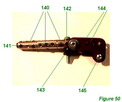
The two Spandau machine guns may now be constructed. Figure 50 shows a gun in isolation. A 1 1/2" axle rod is used to join three couplings 140. The foremost coupling has a black allen bolt 141 fixed in the end, to represent the gun muzzle. The centre bore of the rear coupling has a 1" long bolt 142 screwed through it, with a small rubber pulley143 on the underside, which will be compressed somewhat against the fuselage when the gun is fixed to the front cockpit rim. A 3/4" long bolt passed through the end bore of the coupling holds two 1 1/2" x 1/2" corner brackets 144 (part 133b). Brackets 144 are bolted together at the 'trigger' end using a 1/2" long bolt 145.
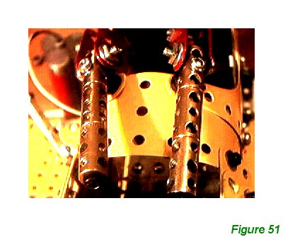
Bolt 142 is used to fix the guns to the front of the cockpit rim. Figure 51 shows the guns in place, bolted to the cockpit rim. The spacing of the gusset plates at the front can also be seen.
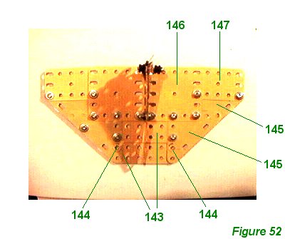
Figure 52 shows the tailplane from above with the tail in place, but without the rudder and elevator flaps.
Two 3" x 1 1/2" flat plates 143 overlap by one row of holes to form a rigid base in the center of the tail. They will be bolted to brackets 43 in the fuselage framework at holes 144 (see Figure 21). Two 2 1/2" x 2 1/2" triangular plates 145, a 2/12" x 2 1/2" flexible plate 146 and a 2 1/2" x 1 1/2" flexible plate 147 form the rest of the sailplane, on each side.
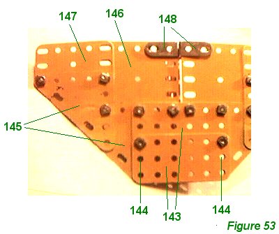
Figure 53 shows the underside of the tailplane. 1" x 1./2" angle brackets 148 carry the tail and are bolted to the hindmost brackets in the fuselage framework.
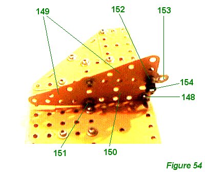
Figure 54 shows the tail. This consists of two 2 1/2" x 1 1/2" triangular plates 149 bolted to a 2 1/2" x 1 1/2" flexible plate `150. 1/2" x 1/2" angle bracket 151 holds the tail to the tailplane, one on each side, and bracket 148 can also be seen. A long 1" bolt 152 carries a hinge 153 which will be fixed to the rudder. Bolt 152 also has a small rubber pulley 154 on each side of the tail; these pulleys act as a guide for the rudder wires. They are somewhat obtrusive and modelers are encouraged to improve upon the design.
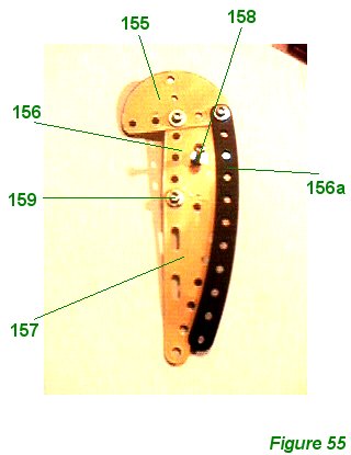
Figure 55 shows the rudder. Two semi-circular plates 155 sandwich a 2 1/2" x 1 1/2" flexible plate 156. Two 5 12" curved perforated strips 156 are also bolted to plates 155 and plate 156, one strip on each side. The slots of plate 156 are used to angle plates 155 downwards somewhat. A 3 1/2" x 1 1/2" triangular flexible plate 157 is bolted to plate 156 so that the longest side forms a straight line with the edge of plate 156. Bolt 158 is a 1" long bolt nutted to plate 156 so it sticks out equally on each side - this bolt carries the two ends of the rudder wire from the rudder control bar in the cockpit. Bolt 159 will also be attached to hinge 153 on the tail.
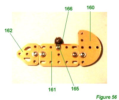
Figure 56 shows the upper side of a tail elevator. A semi-circular plate 160, a 2 1/2" x 1 1/2" flexible plate 161 and a flat trunnion 162 are connected by a 3 1/2" perforated strip 163 on the underside. A 1" x 1/2" narrow angle bracket 165 (part 812b) provides the elevator horn to which one elevator control wire is attached. The same bolt also carries hinge 166.
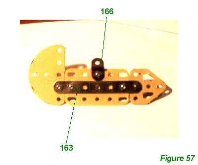
Figure 57 shows the underside of the tail elevator.
INTRODUCTION | PARTS LIST
CONSTRUCTION: Upper Wing | Undercarriage | Fuselage Framework | Airscrew and Engine Block | Cockpit and Joystick | Lower Wings | Fuselage Covering and Wing Struts | Guns and Tailplane |
POSSIBLE IMPROVEMENTS