
The fuselage is a frame of perforated strips covered over with flexible plates. The plates should be bolted onto the framework later, after the lower wings, cockpit controls, engine and airscrew are completed. Naturally all the bolts in the framework will have to be undone and bolted up again with the plates in place later. In the model, many of these are long bolts to aid construction when passing the bolt through several parts at once, or because spacing is used between elements of the framework as the fuselage becomes wider towards the cockpit. Because the fuselage is completely symmetrical, details are given for one side only.
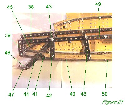
Figure 21 shows the rear end of the framework with the tailskid in place. A 9 1/2" perforated strip 38 is bolted to a 2" perforated strip 39 and to a 1/2" angle bracket with the slot facing inwards. The slot provides a fixture for the tailplane assembly later.
A similar 1/2" x 1/2" bracket is bolted to the bottom hole of strip 39, which carries a 2" perforated strip (the modern 5-hole variety) flat across the width of the base of the fuselage and a 12 1/2" perforated strip 40 flat along the length of the base of the fuselage. Thus at the rear of the fuselage, it will be four holes wide.
A 1/2" x 1/2" bracket 41 will carry a flexible plate later. A 2 1/2" perforated strip 42 is bolted to the slot of a 1/2" x 1/2" bracket at the base, and to strip 38 and the hole of a 1/2" x 1/2" bracket 43 at the top - using modern angle brackets will enable bracket 43 to be placed behind the strips. Note that the slot sticks out from the fuselage, providing another fixture for the tailplane. A double armed crank is bolted behind strip 42 by the top and centre hole of the strip, on each side of the fuselage. The crank bosses form journals for a 2" axle rod, on which the tail-skid is mounted. The tail-skid consists of two 5 1/2" girders 44 bolted together to form a compound U-girder. Bolt them together by the slotted holes, and mount them on the axle rod through the last but one hole. The last hole carries a tension spring 45 which runs back down to the centre hole of the 5-hole 2" perforated strip across the rear of the base of the fuselage. Long 3/8" bolts are used to secure the tension springs - one nut secures the bolt to the strip or girder, and a second nut secures the spring on top.
At the bottom of the tail skid a 1/2" x 1" obtuse angle bracket 46 is bolted to girders 44. A single bent strip 47 is bolted beneath bracket 46.
The tailskid arrangement works but might be improved with extra tension springs to provide a stiffer suspension. In the original aircraft, elastic 'bungee' rope was used, stretching backwards like the spring in the model.
A 3" perforated strip 48 is bolted to the slot of a 1/2" x 1/2" angle bracket at the base and to strip 38 and to a new 12 1/2" perforated strip 49 at the top. Note that there are six clear holes between strips 42 and 48 at the top, but seven clear holes between the two at the base, so the strip is inclined backwards somewhat. At the base, 12 1/2" strip 40 is bolted to a fresh 12 1/2" strip 50, overlapping it by six holes. These base strips will carry something of a curve from rear to nose which provides an effective profile for the aircraft, reasonably to scale within the limitations of Meccano spacing.
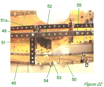
Figure 22 shows the mid-section of the fuselage framework. At the top, a 3 1/.2" perforated strip 51 is bolted to strip 49 and to a 2 1/2" x 1/2" double angle strip. This double angle strip is separated from strip 51 by two washers; in the model, 1/2" long bolts were used here as three flexible plates and a third washer will be added to the outside later. A 2 1/2" x 2 1/2" curved flexible plate 52 (part 200) is bolted to the double angle strip and hangs down to form the pilot's seat.
At the base, strip 51 is secured to a further 2 1/2" x 1/2" double angle strip, which in turn is bolted to strip 50 just in front of the end of strip 40. Note that there are ten holes between strip 48 and strip 51 at the top, but only nine holes between strips 48 and 51 at the base, thus strip 51 inclines forwards somewhat.
A 3/8" long bolt 53 carries a 1" narrow perforated strip 54 (part 810 - a fishplate could be used instead). Strip 54 is hard to see in the picture. It is angled backwards slightly and will be fixed to the inner trailing edge corner of the lower wing. Refer to figure 26 to see exactly where this and other fixture bolts are placed on the underside of the fuselage.
A 2 1./2" x 1/2" double angle strip is bolted to strip 49 at bolt 55, again with two washers spacing it from strip 49, which will carry the cockpit instrument panel.
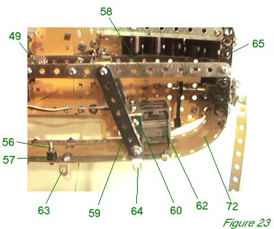
Figure 23 shows the front section of the fuselage framework.
3/4" long bolt 56 has been left in place and will carry the central girder of the lower wing, with plastic collar 57 to space the lower wing from the base of the fuselage. A brass collar could be used instead.
A 5 1/2" perforated strip 58 overlaps strip 49 by three holes. A 3 1/2" perforated strip 59 is bolted in place with a 2 1/2" x 1/2" double angle strip on the inside at the top, spaced from strip 58 by two washers. At the base, strip 59 is bolted to a 2 1/2" x 1 1/2" double angle strip 60, again, separated from it by two washers. A 2 1/2" x 1" double angle strip 61 is bolted over the top of double angle strip 60 and will in turn carry the motor 62. Both of the arm holes of double angle strip 61 are bolted to double angle strip 60, the spacing washers allowing tight room for a bolt head underneath strip 59.
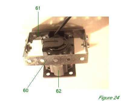
Figure 24 shows the motor assembly in isolation.
A 5 1/2" perforated strip 58 overlaps strip 49 by three holes. A 3 1/2" perforated strip 59 is bolted in place with a 2 1/2" x 1/2" double angle strip on the inside at the top, spaced from strip 58 by two washers. At the base, strip 59 is bolted to a 2 1/2" x 1 1/2" double angle strip 60, again, separated from it by two washers. A 2 1/2" x 1" double angle strip 61 is bolted over the top of double angle strip 60 and will in turn carry the motor 62. Both of the arm holes of double angle strip 61 are bolted to double angle strip 60, the spacing washers allowing tight room for a bolt head underneath strip 59. Figure 24 shows the motor assembly in isolation.
The undercarriage struts will be carried on 1" x 1./2" narrow angle brackets 63 and 64 (part 812b), the long arm of which is bolted between the flexible plates on the base of the fuselage and strip 50. The front bracket, 64, is also bolted to the underside of the motor assembly through the third hole from the end of strip 50. These brackets are opened out slightly with pliers to carry the struts: this is best done after they are in place and the correct angle can accurately be judged.
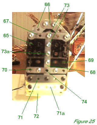
At the nose, 2 1/2" x 1 1/2" flanged plate 65 is bolted to the end of strip 58. Figure 25 shows the radiator from the front, with the airscrew removed. At the top, two obtuse corner brackets 66 (part 133c) are bolted together, and then to flanged plate 65 together with a 2 1./2" narrow perforated strip 67. A 3" narrow perforated strip 68 is bolted vertically and carries a second 2 1/2" x 1 1/2" flanged plate 69. A 2 1/2" narrow perforated strip 70 is bolted across the centre of flanged plate 69. The bolts also hold a double bent strip on the inside of flanged plate 69, to form a journal for the airscrew. A 2 1/2" perforated strip 71 is bolted over a 9 1/2" strip plate 72 and also to flanged plate 69 and strip 70. A second 2 1/2" perforatred strip 79 is also bolted over strip plate 72.
Note that bolts 73 are 1/2" bolts which pass through small rubber pulleys (part 23c) on the inside, and then secure the front cylinder of the engine block, compressing the rubber pulleys somewhere between cylinder and flanged plate. Bolt 73a passes through the hole of a 1/2" x 1/2" angle bracket on the inside of flanged plate 65, the slot of the bracket forming a mounting for the engine block.
Note also that hole 74 will carry the airscrew shaft.
With the motor assembly in place, strip plate 72 is curved back and bolted to strip 50. The seventh hole of plate 72 is bolted to the first hole of strip 50. The various bolts in strip 50 holding fixtures can be removed and replaced with strip plate 72 in position.
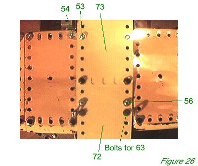
Figure 26 shows strip plate 72 from below, and the bolts previously mentioned. A 9 1/2" strip plate 73 overlaps strip plate 72 by three holes.
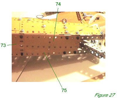
Figure 27 shows the rear of the base of the fuselage with the plates in place. Two 5 1/2" x 1 1/2" flexible plates 74 and 75 are inclined towards each other, overlapping, towards the rear of the fuselage. A gap is left right at the back for the tailskid.
INTRODUCTION | PARTS LIST
CONSTRUCTION: Upper Wing | Undercarriage | Fuselage Framework | Airscrew and Engine Block | Cockpit and Joystick | Lower Wings | Fuselage Covering and Wing Struts | Guns and Tailplane |
POSSIBLE IMPROVEMENTS