
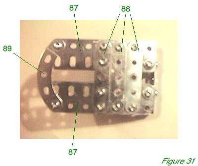
Figure 31 shows the floor of the cockpit. Two 3 1/2" flat girders 87 are joined by three 2 1/2" perforated strips 88, and a 2 1/2" stepped curved perforated strip 89 at the rear of the floor.
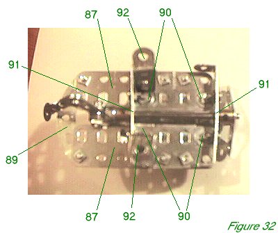
Figure 32 shows the underside of the cockpit floor with the joystick control mechanism in place. Four 1/2" x 1/2" angle brackets 90 are bolted to the floor and carry two 2 1/2" x 1/2" double angle strips 91 into which the aileron control shaft is journalled. Two 1 1/2" x 1/2" double angle strips 92 are also bolted to the cockpit floor and will be bolted in turn to the base of the fuselage as previously described in the Fuselage Framework section.
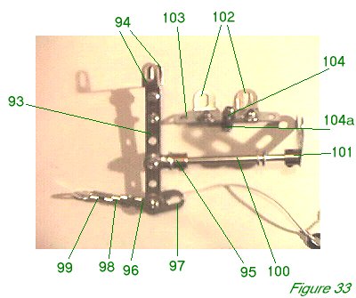
Figure 33 shows the joystick control mechanism in isolation, and the rudder control mechanism beside it.
Two 3" narrow perforated strips 93 are bolted together side by side for strength, and two narrow reverse angle brackets 94 (part 825) are bolted to the top to form the hand grips. A small fork piece 95 is bolted to strips 93 with a 5/8" Allen pivot bolt (a standard pivot bolt will do fine), and three washers on either side of the strips to hold it centrally, but free to move forwards and backwards. A rod and strip connector 96 is bolted to the end hole of strips 93 pointing back towards the tail, along with a fishplate 97 pointing towards the nose. A 3/8" long bolt with a locknut - or two nuts lock-nutted - should be used to allow both the rod and strip connector 96 and fishplate 97 to move freely. Rod and strip connector 96 carries a 1 1/4" axle rod 98 (part 18c) with a second rod and strip connector 99 on the other end. It is not necessary to use this length of axle rod - a 1" or 1 1/2" axle rod would do just as well.
A wire will be passed through the hole of rod and strip connector 99 and both ends drawn through the rear fuselage until they emerge to be connected to the elevator horns in the tail plane so that when the joystick is moved forwards and back, the elevator flaps rise and fall in unison. A length of elastic is tied to fishplate 97. The other end is tied to a second fishplate and this is bolted to a suitable hole in the front fuselage - one of the flat plates is ideal. The elastic tends to pull on the joystick against the weight of the elevator flaps, and thus prevents the elevator flaps from always falling down and dragging the joystick forward as a result.
Fork piece 95 is secured to a 3" axle rod 100 which will be journalled through double angle strips 91. Axle rod 100 carries a bossed bell crank 101. This is secured so that the when the joystick is upright, the arms of the bell crank are spread equally, at 45 degrees to the vertical. A wire will be passed through the two end holes of the bell crank arm and both ends of the wire passed up through the top of the fuselage, through the top wing, and around the pulleys on the top wing until they are attached to the aileron horns as described in the instructions for the Upper Wing. As the joystick is moved from side to side, so the wire will pull one aileron up and, aided by the elastic on the underside of the ailerons, cause the other aileron to droop. The movement is not great, and would not have been in the prototype, but if the wires are taut, it is sufficiently pronounced to demonstrate the control of the ailerons from the joystick.
The rudder control bar is very simple. Two obtuse angle brackets 102 are bolted to a 2 1/2" narrow perforated strip 103 which is secured to the centre hole of the forward-most perforated strip 88 by a 1/2" bolt using a plastic mini spacer 104a (part 38b) and a locknut 104 so the control bar is free to pivot. A wire will be run between the slots of angle brackets 102 and the two ends drawn back through the fuselage to be attached to the rudder.
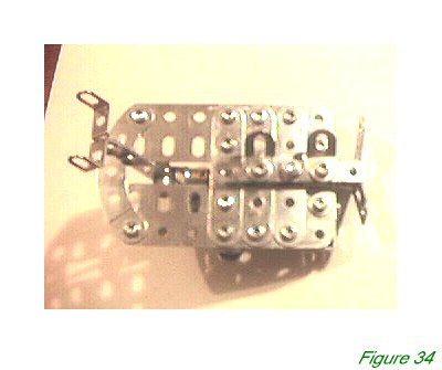
Figure 34 shows the cockpit floor from above with the joystick and rudder mechanisms in place. The picture shows the rudder bar wrongly rotated sideways. The control wires should be placed sooner rather than later - I left them later and cursed greatly as I tried to poke them through inaccessible parts of the fuselage. Make sure you leave plenty of extra wire which can be trimmed later. In particular, when attaching the aileron wire, remember that both ends must pass upwards about eight inches as well as outwards along the wing - an extra foot and a half altogether, almost, on top of the outward span.
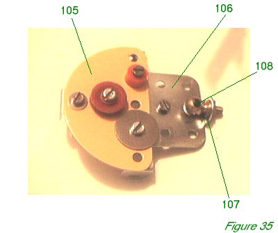
Figure 35 shows the instrument panel. A semi-circular plate 105 is bolted over the 2 1/2" x 1/2" double angle strip previously mentioned and also to a 1 1/2" x 1 !/2" flat plate 106 hanging down below. A 1" x 1/2" angle bracket 107 is bolted to flat plate 106 and carries a handrail support 108 - this represents the compass in its gimbals. A 1/2" plastic pulley, orange plastic spacer, and a large washer are used to represent instrument panels, more or less where larger instrumentation occurred in the original. There is scope for improvement if modelers have photographs of an original Fokker DVII cockpit.
In the model, a further 1" x 1/2" angle bracket was fixed to the top two holes in the centre of plate 105. It was the intention to bolt this, with appropriate spacers, to the fuselage cover, but in fact this was never done. The bracket remains in the parts list, but the bolt and spacers for the connection do not.
INTRODUCTION | PARTS LIST
CONSTRUCTION: Upper Wing | Undercarriage | Fuselage Framework | Airscrew and Engine Block | Cockpit and Joystick | Lower Wings | Fuselage Covering and Wing Struts | Guns and Tailplane |
POSSIBLE IMPROVEMENTS