
The fuselage is covered over with plates. There are many different combinations of platework which are possible, but the model uses plates which were to hand at the time. The pictures show the side plates and the top plates which have been opened out. Refer also to Figures 21-25 for the underlying framework on which the plates are to be bolted.
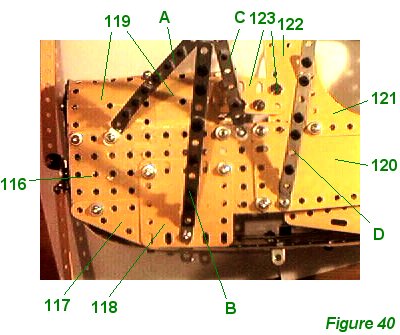
Figure 40 shows the front of the aircraft. A 5 1/2" x 2 1/2" flat plate 116 is bolted over strip 58. 2 1/2" x 1 1/2" triangular plate 117 and 2 1/2" x 2 1/2" flexible plate 118 are bolted to plate 116 as shown. 2 1/2" x 2 1/2" curved flexible plates 119, overlapping each other by one hole, are bolted to plate 116 along the upper edge. These are curved inwards until they almost touch the sleeve pieces in the engine block.
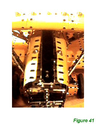
Figure 41 shows an overhead view. However, plates 116, 118 and 119 also carry the forward fuselage wing struts shown as A, B and C. The construction of the struts is discussed at the end of this section.
A 12 1/2" strip plate 120 is bolted to the end holes of plate 116. Strut D is attached to the lower edge of pate 120. A flexible gusset plate 121 is bolted to a 5 1/2" x 1 1/2" flexible plate 122 and to strip plate 120. Plate 121 and 122 will be curved around the top of the fuselage. In the model two 1 1/2" x 1" flat girders 123 are bolted together, overlapping by two holes to form a 2" compound flat girder, are bolted to plate 122. This was an ugly arrangement. The reason for not using a single 2" flat girder was because such girders are not available in light yellow. It is probably much more desirable to use another 5 1/2" x 1 1/2" flexible plate curved around the top of the fuselage. However in the model I decided to leave an opening here so as to be able to adjust the aileron control wired more easily and generally maintain some access to the inner fixtures. Modelers are encouraged to consider improving the construction of this part of the fuselage for themselves.
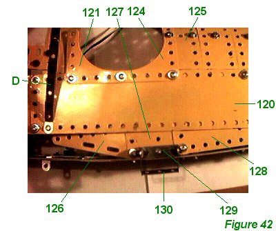
Figure 42 shows the mid-section of the fuselage around the cockpit area. Flexible gusset plate 124 is bolted to gusset plate 121 and strip plate 120 as shown, and, at the rear, to 5 1/2" x 1 1/2" flexible plate 125. Plate 125 is the first of five such plates leading edge to edge back along the fuselage; all these plates are bolted to strip plate 120 (and the corresponding strip plate on the other side) by the second hole from each end. Perforated strips are bolted underneath the central holes of these plates leading backwards, as a connecting spine. In the model, a 4 1/2" perforated strip and 7 1/2" perforated strip were used, overlapping by seven holes, but other combinations are possible.
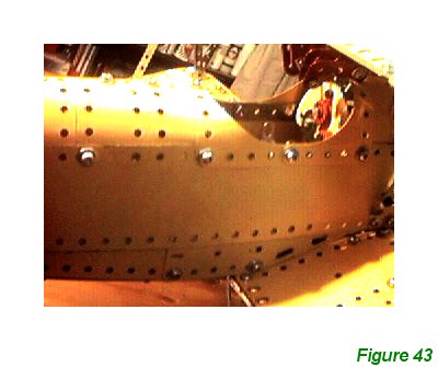
Figure 43 shows a different view of this area, in the finished model. Note that the gusset plates bolt together at the rear of the cockpit, whereas at the front there is a full space between them, as the front of the cockpit is higher than the rear.
A 3 1/2" x 1 1/2" triangular flexible plate 126 is bolted to a 2 1/2" x 1 1/2" flexible plate 127 which in turn is bolted to a 5 1/2" x 1 1/2" flexible plate 128. These plates are arranged so that plate 126 is close to the curve of the lower wing. On the left hand side (as in Figure 42) of the aircraft a 1 1/2" x 1/2" double angle strip 129 is bolted to plate 127. A 1 1/2" x 1" double angle strip 130 is bolted to double angle strip 129 to form a step for the pilot. This structure is not repeated on the right hand side.
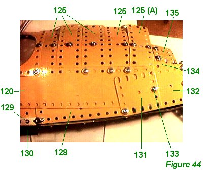
Figure 44 shows the five plates 125 to advantage. 2 1/2" x 2 1/2" flexible plates 131 and 132 are bolted in place as shown - a single 4 1/2" x 2 1/2" flexible plate could be used but it is easy to secure the smaller plates as the space for fingers dwindles.
The hindmost plate 125 marked A in Figure 44 is angled down towards the tail somewhat, and the strip serving as the spine below it must of course also be curved downwards to match. Bolt 133 carries the lower left corner slot of 2 1/2" x 1 1/2" flexible plate 134, to which in turn is bolted 2 1/2" x 1/2" flexible plate 135, curving over the rear of the fuselage.
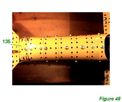
Figure 48 shows an overhead view of the rear of the model with the tail in place. The view also shows how the plates bend down towards the tail.
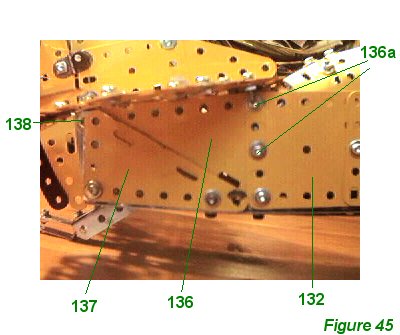
Figure 45 shows the rear of the model from the side, again with the tail in place. Bolts 136a are 1/2" long bolts which pass through strip 42 and the double arm crank carrying the tailskid axle rod, as well as 3 1/2" x 2 1/2" flexible triangular plate 136. 3 1/2" x 2" flexible triangular plate 137 is bolted into the remaining space. Note that plate 137 just rests over bolt 138 right at the back.
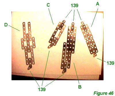
Figure 46 shows wing struts A, B, C, and D - all attached to the fuselage as described above - in a disassembled state. Narrow strips are used to build these strips up with obtuse narrow angle brackets 139 to attach them at appropriate angles to fuselage and upper wing.
The exact choice of narrow strips used is irrelevant as long as a strong strut is formed. The choice of narrow strips used in the model reflects what was available to me when the model was built, and is recorded in the list of parts, but can be improved upon. Whichever strips are chosen, however, it is useful to alternate shorter strips with long ones to leave slots in the end for the angle brackets and to interleave the strips from different struts, where two struts meet, in order to create stronger joints.
Struts A, B and C all meet at the top and are bolted using a long 1/2" bolt to the 1" x 1/2" angle bracket in the upper wing.
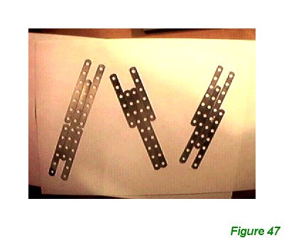
Figure 47 shows the three outer wing struts disassembled as before and Figure 49 shows a side view of them attached between the upper and lower wings.
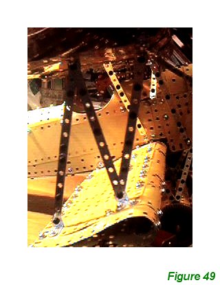
Figure 49 shows a side view of them attached between the upper and lower wings.
At long last the undercarriage and the upper wing may now be bolted to the fuselage and wing struts, and the aileron wires pushed through the centre flat plates of the upper wing, over their pulleys and adjusted on the aileron horns.
INTRODUCTION | PARTS LIST
CONSTRUCTION: Upper Wing | Undercarriage | Fuselage Framework | Airscrew and Engine Block | Cockpit and Joystick | Lower Wings | Fuselage Covering and Wing Struts | Guns and Tailplane |
POSSIBLE IMPROVEMENTS