
The undercarriage has a frame of perforated and double angle strips, covered over with rows of curved 2 1/2" x 1 1/2" flexible plates. In the model, yellow plastic plates where used, as the plastic is well suited to the curve required. But there is no reason why metal flexible plates cannot be used.
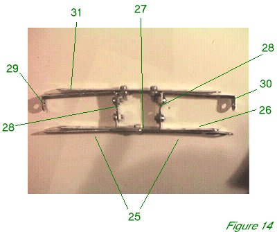
Bolt two 3 1/2" perforated strips 25 and a 5 1/2" perforated strip 26 to a 1 1/2" x 1/2" double angle strip 27, as shown in Figure 14, to make an assembly 13 holes wide. Bolt two 1" x 1/2" angle brackets 28 to the arms of double angle strip 27, with the brackets turned inwards. Bolt two 2 1/2" x 1/2" double angle strips 29 and 30 to brackets 28. Bolt a 5 1/2" perforated strip 31 across the top of double angle strips 30 and brackets 28, using spacing washers when bolting to the brackets, which are most likely on a slightly lower level. These last bolts will carry four plates each and another washer when the undercarriage is finally finished, and in the model long 3/8" bolts were used. The picture shows the strips and brackets loosely bolted, so that they can be seen more easily, but in the model they must be bolted together very tightly.
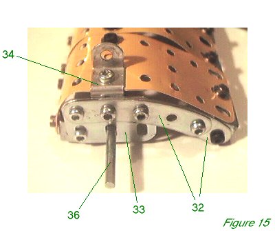
Figure 15 shows an end-on view of the framework including the covering plates. Two 2 1/2" curved strips 32 are bolted to a 1 1/2" flat girder 33. Curved strips 32 only overlap by one hole, so as to form a 3" curve. A reverse double angle bracket 34 is bolted to the centre hole of flat girder 33 on the inner side, the other end of which will form a strong bracket for the undercarriage struts, but it will probably be easiest to bolt this in place at the end, even if it means some slight disassembly to do it.
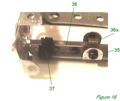
Figure 16 shows the inside of the construction in detail on the right hand side. Slide a double angle bracket 35 between strips 25 and 27. Set a collar 36 between the jaws of bracket 35 using a standard bolt on each side to hold it. Slide a 3" axle rod 36 through the centre slot of flat girder 33, and then through the loop of a 6" driving band 37. Wrap driving band 37 around strips 25 and 27 twice, and then secure by pushing the loop once again over the end of axle rod 36. Push the axle rod into collar 36 and secure it. The axle rod will now move up and down a little in the slot, while the looped driving band acts as 'bungee rope' suspension, as in the original aircraft.
On the outer side, axle rod 36 carries a loose collar, a 2" pulley with tyre (part 142a), a conical disc to act as the wheel cover, a washer, and finally a second collar is secured to the end of the rod to hold it all in place.
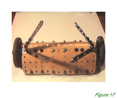
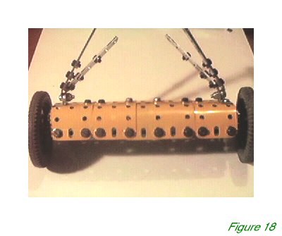
The construction can now be covered over with the flexible plates. The front set of five are bolted to strip 31 by their fourth holes, and the rear set also to strip 31, over the front set, by their first holes. Bolt two angle brackets to the front slots of flat girders 33 and join them with two 2 1/2" strips and a 4 1/2" strip, overlapping to make a thirteen-hole compound strip. At the rear the model uses two 2 1/2" x 1/2" double angle strips and one 1 1/2" x 1/2" double angle strip bolted together and to the end holes of curved strips 32 to achieve the same effect. The flexible plates are then curved and bolted firmly down on the front and rear bars. With thirteen holes to span, the simplest arrangement is to have one central flexible plate in each group of five overlapped on either side: Figures 17 and 18 show the complete undercarriage unit from front and back.
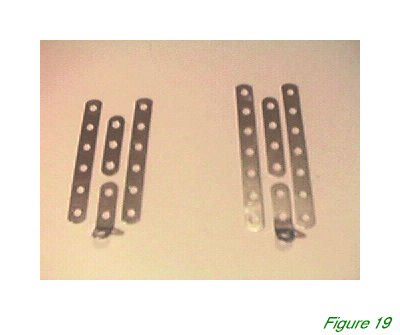 Narrow strips are used for the undercarriage struts, built up with several thicknesses for strength. Figure 19 shows the struts disassembled. The rear left and right struts are six holes long and consists of two 3" narrow strips with a 1 1/2" narrow strip and a 1" x 1/2" obtuse narrow angle bracket (part 812c) sandwiched between them. The front strut is almost identical, except it is 3 1/2" long, and therefore uses two 3 1/2" narrow strips with a 2" narrow strip and 1" x 1/2" obtuse narrow angle bracket (part 812c) sandwiched between them. This leaves a one hole slot in the top of each strip to carry the end of the bracket in the fuselage to which they will later be attached.
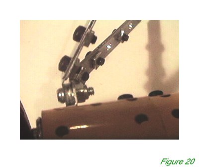 The ends of the narrow obtuse angle brackets are attached to the end of the reverse double angle bracket 34 by means of a 3/8" long bolt and locknut (part 37h). As always, two ordinary nuts can be locknutted together to make a similarly strong joint, although the modern French locknuts are easier to use. The front strut is on the outside, and spaced from the rear strut by two washers, which leaves room for them to splay out without interfering with each other. Figure 20 shows the struts bolted in place, in close detail.
INTRODUCTION | PARTS LIST
CONSTRUCTION: Upper Wing | Undercarriage | Fuselage Framework | Airscrew and Engine Block | Cockpit and Joystick | Lower Wings | Fuselage Covering and Wing Struts | Guns and Tailplane |
POSSIBLE IMPROVEMENTS