
The lower wings are built in a very similar style to the upper wings, but as they carry no ailerons, and are in two distinct halves, they are even simpler.
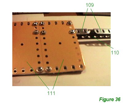
The central girder is slightly different. Figure 36 shows the central area. Two 12 1/2" angle girders 109 are bolted to a central 5 1/2" angle girder 110, overlapping by five holes on either side. The base of girder 110 is bolted very tightly to the fuselage using long bolts 56, spaced from the fuselage base by plastic spacers or collars as described in the Fuselage Framework section.
It is important to bolt the girders in place at this stage as will not be possible to pass the wings through the fuselage when they are fully built-up.
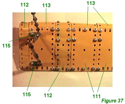
Working from the inside out, Figure 36 shows the inner part of the wing and Figure 37 shows the outer part of the wing. Construction is almost identical to the upper wing, except that eight 4 1/2" x 2 1/2" flexible plates 111 are used on each wing, four on the upper surface and four on the underside. Four 5 1/2" x 1 1/2" flexible plates 112 are also used on each wing, two on the upper surface and two on the underside: the plate at the wingtip overlaps the next plate by one hole.
Four 2 1/2" x 2 1/2" curved flexible plates 113 (part 199) are used for the leading edge on each side, but flexible plates 112 are long enough to be curved right round the leading edge and bolted together at their ends.
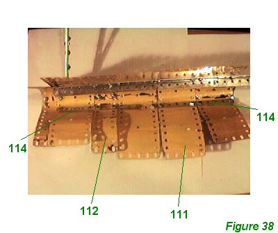
On the upper side the flexible plates are bolted to girder 109, but also connected at leading and trailing edges by 5 1/2" perforated strips 114. Two are used to bolt the trailing edges together, and four are used at the leading edge - two for the upper side and two for the underside. Figure 38 shows the plates of a lower wing opened out to show the strips and the leading edge.
In Figure 37 the wing struts have been left in place to show how they are attached. They are bolted to the lower wing by means of two 1" x 1/2" angle brackets 115. In the model locknuts were used on the bolts to make as strong and tight a fixture as possible.
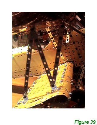
Figure 39 shows a side view of the lower wing.
INTRODUCTION | PARTS LIST
CONSTRUCTION:Upper Wing | Undercarriage | Fuselage Framework | Airscrew and Engine Block | Cockpit and Joystick | Lower Wings | Fuselage Covering and Wing Struts | Guns and Tailplane |
POSSIBLE IMPROVEMENTS