
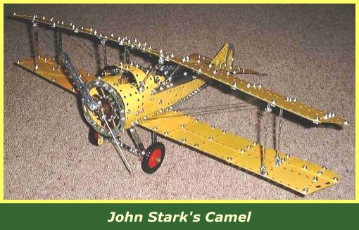
John Stark in New Zealand has an elegant solution to the problem of squeezing a motor into the front fuselage section of the model.
He uses a non-Meccano motor to power the aircraft and mounts it in the tail section. Two flexible rod connectors (part 213c) are used as compact universal joints to transfer the drive forward.
To the rear end of the crankshaft attach a 1" pulley with boss. Below this (just above the floor level) is an axle with a 1/4" rubber pulley (part 23c). The 1" pulley and rubber pulley are connected with a 2.5" driving band.
Two 1/2" angle brackets are bolted to the floor of the cockpit under the pilot's seat through their slotted holes with their uprights facing each other to provide a bearing for the rear end of the floor axle.
A collar and black plastic spacer (part 38a) are placed between the angle brackets to hold the axle in position.
The rear end of the axle carries a flexible rod connector, which is connected to a short axle. This short axle is connect to another 213c on the motor shaft.
The precise lengths of axles depends on the location of the motor. The rubber flexible rod connectors are much more compact and quieter than the metal universal coupling. John also preferred to use pulleys rather than gears. When working, he says, there was just enough imbalance in the nine cylinder motor (perhaps due to the different vintages of worms used) to make the plane vibrate slightly. The sound was quite realistic!
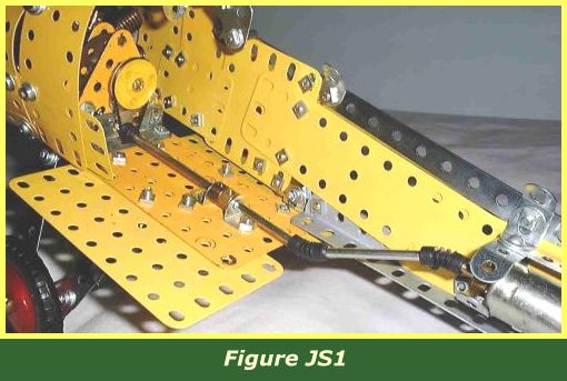
Figure JS1 shows how the transmission from motor to airscrew is effected. John built up the sides of his version with flexible plates rather than strips and attached the rear section differently as well.
In the same photo, there is a 1/2" angle bracket with its round hole sandwiched between the flat plates in the second to last hole of the 5.5"x2.5" flat plate. This carries a 3/8" bolt, washer, and nut leaving the threaded end facing outwards to attach the side of the tail section.
A bush wheel has been used instead of a crank for the main bearing of the airscrew shaft, and long bolts have been used on the fourth hole down from the top on each side, to give rigidity to the assembly in place of the original threaded pin at the top.
INTRODUCTION | PARTS LIST
CONSTRUCTION: Rotary Engine | Illingworth Rotary Engine | Engine Cowling | Undercarriage | Fuselage, Front Section I | Front Fuselage Canopy and Cockpit Details | Rear Fuselage Section | Front Fuselage Section II | Upper and Lower Front Wings | Tail Section | Wing Assembly and Stringing
POSSIBLE IMPROVEMENTS