
The wire for the motor should be passed through a suitable exit place at this point.
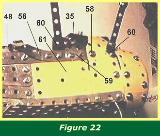
Figure 22 shows how 12 1/2" strip 48 is attached to the front fuselage section. In fact the end hole of the strip is secured with bolt 58.
Figure 23 shows the underside where the rear and front fuselage sections join. The Allen bolts at the top have two washers under them and bolt to the last hole of the 4 1/2" girders in the rear fuselage.
All three slotted bolts in the centre pass through the three centre holes of a 2 1/2" x 1/2" double angle strip on the other side. The outer bolts of these three have a single washer placed between the two flat plates to tilt the wing supports.
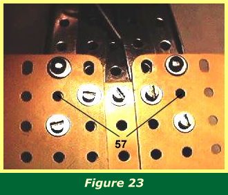
The 1 1/2" strips 45 are pushed under the angle strip and bolted to holes 57.
The two slotted bolts at the bottom of the picture do not have washers between the plates.
Figure 22 also shows the formation of the cockpit rim, with two 2 1/2" curved stepped strips 56 at the rear, and two 2 1/2" curved strips part 59 at the front. The curved strips are all bent inwards around the lines of the fuselage. The front strips are secured to a 3" strip 35 (Figure 16), also bent around the front fuselage canopy, while the rear strips are secured to 1 1/2" strip 55 (Figure 21).
Four obtuse angle brackets 60 should also be fixed to the front fuselage to carry the inner wing struts. It is not difficult to place the nuts for the front brackets if the gun control levers are swivelled sideways.
The cockpit details should now be installed if they have not already been bolted in place.
Two 2 1/2" x 2 1/2" flexible plates 61 form the sides of the cockpit, and are bolted in after everything else is installed. Note that there are no bolts holding these plates at the bottom edge. This makes it easy to remove and replace the plates should any adjustment to the cockpit interior be required. It may be necessary to remove the pilot's chair in order to bolt the rear fuselage in place, for example.
When the rear fuselage section is bolted to the front fuselage section, note that 12 1/2" strip 48 will of course form a straight horizontal line along the fuselage. So the girders and base of the rear fuselage are canted up, and the short strips bolting them to the base of the front fuselage under the double angle strip are bent to the appropriate angle.
INTRODUCTION | PARTS LIST
CONSTRUCTION: Rotary Engine | Illingworth Rotary Engine | Engine Cowling | Undercarriage | Fuselage, Front Section I | Front Fuselage Canopy and Cockpit Details | Rear Fuselage Section | Front Fuselage Section II | Upper and Lower Front Wings | Tail Section | Wing Assembly and Stringing
POSSIBLE IMPROVEMENTS