
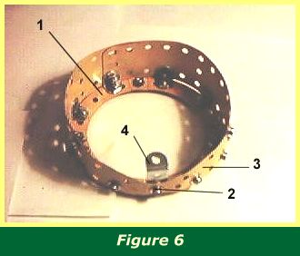
Begin with the four 3" stepped curved strips 1, part 89a (Figure 6) and bolt these together, and to 1/2"x1/2" angle bracket 2 at the bottom.
Bolt two 2 1/2" x 1 1/2" triangular flexible plates 3 to angle bracket 2 and to the slot of 1" by 1 1/2" angle bracket 4. A reverse angle bracket (Figure 11, 22) will later be bolted into the angle of bracket 4, when the front fuselage is constructed.
Two 5 1/2" x 1 1/2" flexible plates, overlapping at the top by four holes, complete the assembly. Eight angle brackets are bolted to the plates through the slots in the strips where the plate holes align.
INTRODUCTION | PARTS LIST
CONSTRUCTION: Rotary Engine | Illingworth Rotary Engine | Engine Cowling | Undercarriage | Fuselage, Front Section I | Front Fuselage Canopy and Cockpit Details | Rear Fuselage Section | Front Fuselage Section II | Upper and Lower Front Wings | Tail Section | Wing Assembly and Stringing
POSSIBLE IMPROVEMENTS