
In building the model, the general sequence of these instructions should be followed.
Note: The photographs referred to in the text are mostly clear enough when printed as black and white hard copy. Some detail may be lost, however, so if you will not have access to a computer when you build the model, it might be wise to make notes about any important information which is not clear in your printout while you can still see the original image! Long bolts and washers for spacing are not mentioned in all occasions. It should be obvious when building when these are required, but not mentioned.
Construction should begin with the Clerget 9-cylinder Rotary Engine. Nine bolts are spaced around the flange of a 1 1/4" flanged wheel with a nut and washer on each side of the flange, the bolt head being on the inner side of the flange. Standard Meccano 3/8" washers are very slightly too large for this operation and the model used non-standard washers of 11/32" diameter and about half the thickness of a standard dished washer.
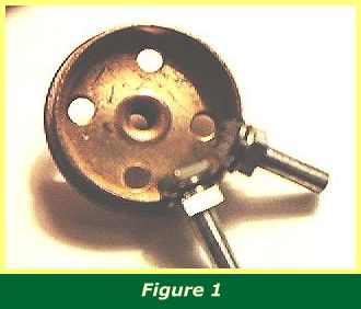
In the model, 1/2" bolts were used but if you are concerned about damage to the screw threads, you could try 5/8" threaded pins instead, as shown in Figure 1. Thin washers are essential using threaded pins, for there will otherwise be little screw thread protruding on the inside to secure the nut.
Attach the bolts or pins to the rim at approximate equal intervals and tighten only sufficiently to hold them lightly in place. Carefully fit the rim of a second flanged wheel between the washers.
This is best accomplished by easing the rim between two or three adjacent sets of washers and gripping it firmly with your fingers to hold them in place. Then work around the circle of bolts. Loosen each nut in turn as much as is needed to make sure both washers are seated on either side of the rim, and then tighten again enough to hold them in place. It is impossible to fully tighten each nut and bolt at this stage, because the inner side is obscured, so do not try.
Once all the bolts are in place, with washers seated either side of the rim, push a 3 1/2" rod through the bosses of the flange wheels and lock the grub screws to ensure the two flanged wheels do not separate. You can now relax your grip!
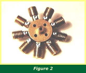
Worms may now be placed over each bolt and secured. The model uses 3/8" Allen bolts as set screws, which gives a pleasing effect both in repose and rotation (see Figure 2).
The nuts can now be tightened against the outer rim, the worm providing a suitable grip for the fingers to hold the bolt still. When the nut is tight, the worm can be loosened and pushed down the bolt to fit snugly against the nut where it can be locked in place with the set screw.
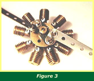
Figure 3 shows the completed assembly with the airscrew attached. The airscrew is a double arm crank to which obtuse angle brackets are bolted, the obtuse faces opposing each other. A pair of 4 1/2" strips are bolted to the obtuse faces.
It is important for the nuts to be as tight and secure as possible, and for the worms to be tightly seated as well, as the whole assembly will rotate and a loose worm flying away from the fixture at speed can damage more than the model!
INTRODUCTION | PARTS LIST
CONSTRUCTION: Rotary Engine | Illingworth Rotary Engine | Engine Cowling | Undercarriage | Fuselage, Front Section I | Front Fuselage Canopy and Cockpit Details | Rear Fuselage Section | Front Fuselage Section II | Upper and Lower Front Wings | Tail Section | Wing Assembly and Stringing
POSSIBLE IMPROVEMENTS