
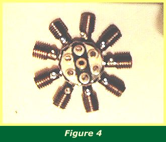
An alternative and most elegant method by George Illingworth (Figure 4) is provided for modellers who cannot obtain suitable washers, or who wish to use only standard parts.
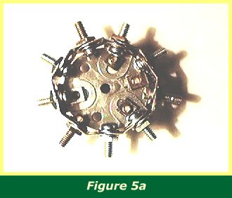
Instead of flanged wheels, make a ring of nine obtuse angle brackets (Figure 5a). The obtuse angle should be widened just a little from the standard 135 degrees, and the brackets arranged alternately, one 'outside' and one 'inside' the circle, as far as possible (there being an odd number). The slotted hole of one bracket must always be bolted to the round hole of the next, using the long bolts or threaded pins on which the worms will be placed.
Every third bolt also passes through the round hole of an angle bracket, and these three brackets are secured to a six hole wheel disc. Once the wheel disc is in place, it is easy to see which if any brackets need more or less bending, and the slots can be used to fit them more accurately around the rim to provide equal spacing between each hole.
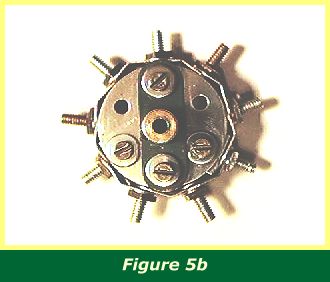
A view of the front of the assembly (Figure 5b) shows a double arm crank secured to the wheel disc to provide a journal for the crankshaft. Washers are used under the arms of the crank to raise it slightly above the washers securing the angle brackets. The remaining empty holes in the wheel disc can be filled with bolts and washers so as to provide a uniform appearance.
This engine is 1/4" wider in radius than the solution with flanged wheels, and is thus a little more difficult to fit into the engine cowling while ensuring that the worms are free to turn without hitting any protruding bolts. It can be done, but the arrangement of bolts and plates described in Section 2 (Engine Cowling) may need to be modified and adjustments made to the exact positioning of the engine on the crankshaft. George Illingworth also suggests using 3/4" washers to build up the engine cylinders, which will look slightly more in proportion than worms with this larger engine.
INTRODUCTION | PARTS LIST
CONSTRUCTION: Rotary Engine | Illingworth Rotary Engine | Engine Cowling | Undercarriage | Fuselage, Front Section I | Front Fuselage Canopy and Cockpit Details | Rear Fuselage Section | Front Fuselage Section II | Upper and Lower Front Wings | Tail Section | Wing Assembly and Stringing
POSSIBLE IMPROVEMENTS