
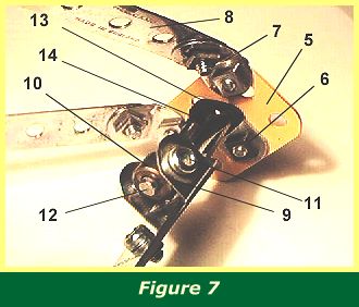
The Sopwith Camel used an elastic cord suspension system in the undercarriage. Figure 7 shows a detail of the suspension.
A 1 1/2" flat girder 5 is bolted to each end of 4 1/2" x 1/2" angle strip 6. Obtuse angle brackets 7 and 2 1/2" strips 8 are bolted to flat girder 5. Double angle bracket 9 holds collar 10 with two bolts 11, one on each side. 2 1/2" rod 12 is pushed through the collar.
The rod is then pushed through the loop of a 2 1/2" light driving band 13. The driving band 13 is then pulled under angle strip 6, around it, and the rod pushed through the loop of the driving band again. The rod is now pushed through the centre slot in flat girder 5. A plastic road wheel part 187, not shown in Figure 7, is pushed loosely onto the rod, and a collar then secures it.
Spring clip 14 is fixed to the rod to hold the driving band in place close to the flat girder.
The same assembly is constructed on the other end of angle strip 6. When completed, a 3 1/2" strip is bolted to the 4th and 6th holes of the angle strip, allowing a tongue of the 3 1/2" strip on each side to hold double angle bracket 9 in place.
Rod 12 is now free to move slightly up and down in the slot of flat girder 5, with suspension provided by driving band 13.
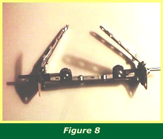
Figure 8 [needs attention!] shows the whole undercarriage assembly.
Four obtuse angle brackets are bolted to the top end of the 2 1/2" strips, to be attached later to the fuselage. Both these and the four obtuse angle brackets will need to bent a little so that the upper brackets are three inches apart along the length of the fuselage and 2 1/2" apart along the width of the fuselage, and yet can still be bolted flat to the base of the fuselage.
INTRODUCTION | PARTS LIST
CONSTRUCTION: Rotary Engine | Illingworth Rotary Engine | Engine Cowling | Undercarriage | Fuselage, Front Section I | Front Fuselage Canopy and Cockpit Details | Rear Fuselage Section | Front Fuselage Section II | Upper and Lower Front Wings | Tail Section | Wing Assembly and Stringing
POSSIBLE IMPROVEMENTS