
|
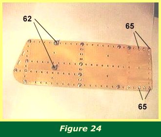
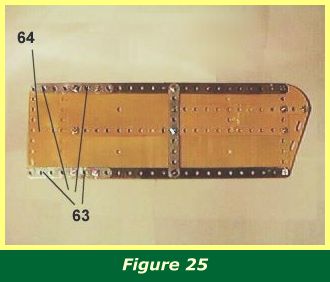
Figures 24 & 25 show the top and bottom of one of the lower wings. Note in Figure 24, 1/2" angle brackets 62, which will carry the wing struts. The underside of the wing is strengthened with strips. 2 1/2" strips 63 will slip under the flat plates 23 in Figure 11, while the 4 1/2" x 2 1/2" flexible plate 64 will slip over the flat plates. The lower wings are pushed flush with the fuselage and bolted in place at holes 65. |
|
|
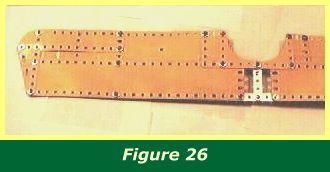
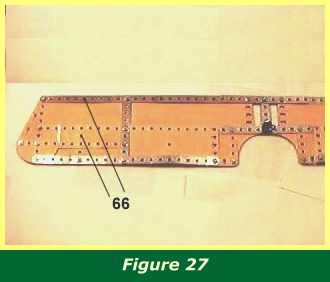
Figure 26 shows half of the upper wing, and the area of the wing over the cockpit, while Figure 27 shows the underside of the same area of wing. Note holes 66 where the outer wing struts will be attached. |
|
|
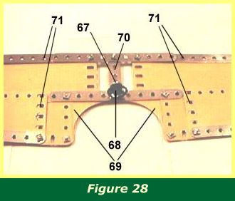
Figure 28 shows the underside of the centre section in better detail. Note 1/2" angle bracket 67. The slot of the angle bracket hangs down to form the gunsight mounting. In the model, the small Meccano plastic steering wheel 68 (part 132), is bolted to the angle bracket slot, making an effective gunsight. In the centre of the upper wing, flexible gusset plates 69 form the cutout above the cockpit, and two slits are formed with 2 1/2" strip 70 which increased pilot visibility. Note holes 71 where the inner wing struts will be fixed. |
|
INTRODUCTION | PARTS LIST
CONSTRUCTION: Rotary Engine | Illingworth Rotary Engine | Engine Cowling | Undercarriage | Fuselage, Front Section I | Front Fuselage Canopy and Cockpit Details | Rear Fuselage Section | Front Fuselage Section II | Upper and Lower Front Wings | Tail Section | Wing Assembly and Stringing
POSSIBLE IMPROVEMENTS