
The rear fuselage is made up of perforated strips. The whole of the rear fuselage section is going to be tilted so that the base slopes upwards towards the front fuselage section. More details of this are given in Section 7 and both this and Section 7 should be read right through before attempting to bolt the two halves of the model together.
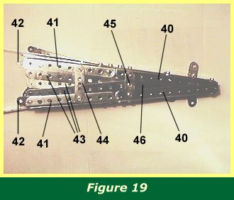
Figure 19 shows the underside of the rear fuselage section and in particular the two 5 1/2" girders 40 and two 4 1/2" girders 41 which are the base of the frame. Note the two 1 1/2" strips 42 bolted to girders 41, the ends of which will be bolted underneath a 2 1/2" double angle strip in the front fuselage section, as described later.
The base is filled in with three fanned 5 1/2" strips 43 passing over a 2" strip 44, before being secured to a 1 1/2" strip 45. A single 2 1/2" strip 46 extends from strip 45 back towards the tail.
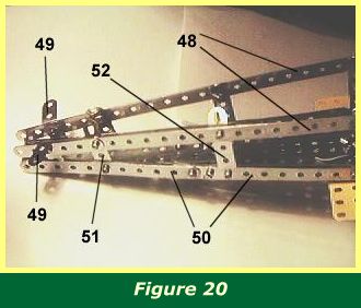
Figure 20 shows the framework for the rear fuselage section. Two 12 1/2" strips 48 extend from the front fuselage canopy back to the bolt securing 1" angle brackets 49. Angle brackets 49 will later support the tail plane wings. The slotted sides of the girders in the base are covered over with 5 1/2" strips 50. The girders themselves are joined with 2 1/2" strips laid along the inside of the girders.
The sides are filled in with perforated strips. As two 12.5" strips 48 are used, the rest of the side panels can be filled in with whatever strips are available.
Obtuse angle brackets are fixed at intervals along the top of the section to carry the strips which form the curved top of the rear fuselage.
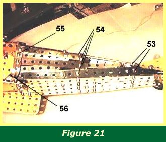
This is shown in Figure 21 where a combination of strips and narrow strips make up the structure. Bolts 53 pass through a 5 1/2" strip, a 2 1/2" narrow strip, and an obtuse angle bracket. The picture is rather dark, but the 2 1/2" narrow strips have three holes under the 5 1/2" strip and two holes protruding, running alongside the yellow tailplane on either side. Bolts 54 have fishplates underneath to hold the strips together. At the cockpit end of the section, the sequence is obtuse angle bracket - fishplate - 1 1/2" strip 55 - fishplate - obtuse angle bracket. Some of the bolts are obscured by 2 1/2" curved stepped strips 56 which are bent around to form the rear rim of the cockpit.
INTRODUCTION | PARTS LIST
CONSTRUCTION: Rotary Engine | Illingworth Rotary Engine | Engine Cowling | Undercarriage | Fuselage, Front Section I | Front Fuselage Canopy and Cockpit Details | Rear Fuselage Section | Front Fuselage Section II | Upper and Lower Front Wings | Tail Section | Wing Assembly and Stringing
POSSIBLE IMPROVEMENTS