
|
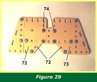
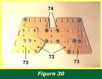
The tailplane wings are shown in Figures 29 & 30. Note the flat trunnions 72 which bolt through the centre hole of 1 1/2" x 2 1/2" flexible plates 73. Holes 74 in the tailplane wings bolt onto the inner holes of the 1" angle brackets protruding from the rear fuselage. It may be necessary to squeeze the rear fuselage tightly in order to place the structure, in which case I recommend strengthening the fixture by bolting a 1 1/2" strip between the holes, resting between the tailplane wings and the angle brackets. |
|
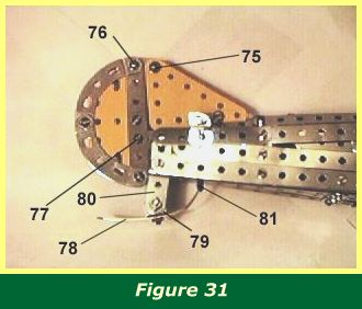
The rudder, vertical tail and tailskid are shown in Figure 31.
Two 2" x 2 1/2" triangular flexible plates are sandwiched either side of a fishplate by bolt 75. Four curved stepped 2 1/2" strips, two on each side, form the outer edge of the rudder, and a pair of 3 1/2" strips form the inner edge. The fishplate securing the triangular flexible plates is bolted to the rudder at bolt 76. A 1 1/2" x 2 1/2" flexible plate is set between the strips forming the rudder.
A second fishplate at bolt 77 leads into the rear of the fuselage. The other end of the fishplate is bolted onto a 5/8" bolt, part 111c, secured on the end of the bolt by two nuts, to make sure it protrudes from the centre of the fuselage and not one side.
The tailskid is built from a formed slotted strip 78 mounted on a double angle bracket 79. This in turn is fixed by a long pivot bolt, (part 147g), to a 1" x 1/2" double angle bracket 80 bolted into the last hole in the base of the fuselage, where the two girders meet. Any bolt or threaded pin of suitable length could be used to fix the skid in place. The other end of strip 78 is attached to a rubber band 81 which passes up into the rear fuselage where it is secured, to provide elastic suspension for the tailskid.
INTRODUCTION | PARTS LIST
CONSTRUCTION: Rotary Engine | Illingworth Rotary Engine | Engine Cowling | Undercarriage | Fuselage, Front Section I | Front Fuselage Canopy and Cockpit Details | Rear Fuselage Section | Front Fuselage Section II | Upper and Lower Front Wings | Tail Section | Wing Assembly and Stringing
POSSIBLE IMPROVEMENTS