
Having made sure the engine is properly aligned and the motor functioning well, remove the cowling again and attach the front fuselage canopy and guns.
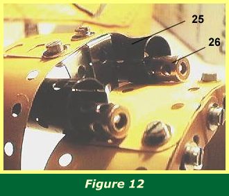
Figure 12 shows the guns consisting of two sleeve pieces 25 with a coupling 26 inside each one. These are held in place by a bolt each through the underside of the engine cowling.
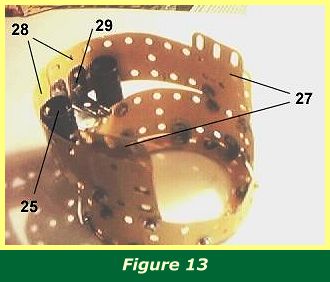
Figure 13 shows the inside of the cowling and front fuselage canopy. A 2 1/2" x 1 1/2" flexible plate 27 is bolted to the inside of the engine cowling on each side. This plate is bent, first convex and then concave, so the front fuselage canopy eventually follows the lines of the fuselage, narrowing towards the tail.
Two 5 1/2" x 2 1/2" plates 28 are bolted to plates 27 and curved around over the tops of sleeve pieces 25 where they overlap by two holes. They are bolted together with two 1" x 1" angle brackets 29 attached to the underside.
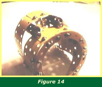
Figure 14 gives a front view of the complete unit. Before it is bolted back on, the cockpit instrument panel and gun levers should be completed.
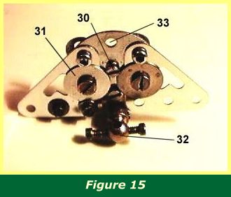
Figure 15 shows the cockpit instrument panel. The back consists of a six-hole wheel disc flanked by two 1 1/2" corner brackets, part 133. One end of a 1 1/2" strip is bolted to the centre hole 30, behind the wheel disc, hanging downwards. Brass bolts, zinc Allen bolts and large and small washers are used to build up the control dials. The large 3/4" washers 31 are secured by pivot bolts with plastic spacers (part 38b) placed behind them but collars could be used. A handrail coupling 32 with two brass bolts represents the control column, although the motor prevents the modelling of a column, and instead the coupling is held on the lowest hole of the 1 1/2" strip by a collar and 1" rod.
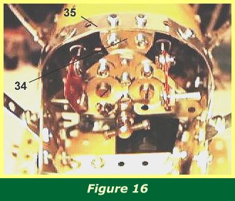
The instrument panel is bolted to a 1" triangular flat plate 34 at the top. The other two holes in the triangular flat plate will be bolted to the front fuselage canopy by means of angle brackets. The bolts concerned will also pass through a 3" strip 35 curved around the front fuselage canopy. These details can be easily seen in Figure 16.
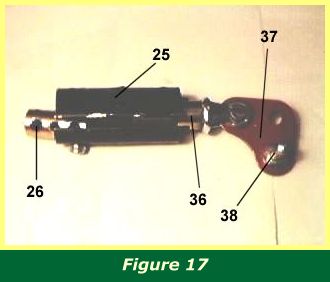
A whole gun assembly is pictured in Figure 17.
The gun levers are mounted on chimney adapters. A bolt secures an end bearing 36 to the top of the chimney adapter. A 1" corner bracket 37 is bolted between the jaws of the end bearing, with washers between bearing jaw and bracket on each side. A 3/4" threaded pin 38 is bolted to the corner bracket to represent the Bowden levers which fired the guns.
The chimney adapters can then be squeezed into the ends of the sleeve pieces 25.
The instrument panel should now be bolted onto the front fuselage canopy.
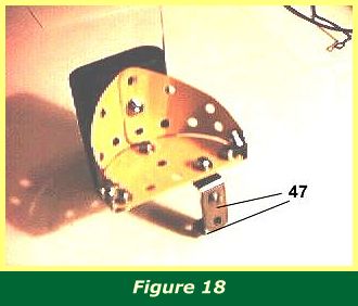
The final detail for the interior of the cockpit is the pilot's chair. This is shown in Figure 18. It is a simple construction of two 2 1/2" x 1 1/2" triangular flexible plates bent around a semi- circular flat plate. In the model, a black plastic Meccano motor battery case, with the switch end removed, is bolted to the rear of the chair to represent the fuel tank, using the long 1" (part 111e) bolt supplied with the battery case. It would also be easy to manufacture a suitable tank, for example, by using flexible plates.
Two 1" x 1/2" angle brackets 47 are used to form a makeshift 1" x 1/2" double angle strip and the chair is bolted to flat plate 16 by means of this. In Fig 11 the bolt in question will pass through hole 39.
Once these features are installed, it is time to turn to the rear fuselage section. Figure 16 shows the completed cockpit with the sides and inner wings struts in place, which will be described later.
INTRODUCTION | PARTS LIST
CONSTRUCTION: Rotary Engine | Illingworth Rotary Engine | Engine Cowling | Undercarriage | Fuselage, Front Section I | Front Fuselage Canopy and Cockpit Details | Rear Fuselage Section | Front Fuselage Section II | Upper and Lower Front Wings | Tail Section | Wing Assembly and Stringing
POSSIBLE IMPROVEMENTS